


Special offers from our partners!

Find Replacement BBQ Parts for 20,308 Models. Repair your BBQ today.
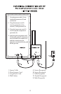
How to Assemble the
Bradley Digital Smoker®
1. Remove smoker from box.
2. Take all packaged parts out of
smoker.
3. Remove all protective packaging
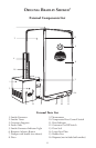
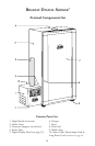
Install Digital Smoke Generator:
• Attach digital smoke generator (1)
to the smoker tower (2) by placing
the Bisquette Burner (E) through
the left side opening of the tower.
Align the generator keyholes to the
two supports (3) on the side and
push down to secure in position.
•Insert the feeder tube (4) into
the top of the smoke generator.
Push down rmly. Load with
desired number of Bradley Flavor
Bisquettes®.
Electrical Connection Set Up (see page 12)
•Plug the Sensor Cable (1) into the
back of the Smoke Generator (A)
and Smoker (B).
• Plug the Short Jumper Cord
(2) into the back of the Smoke
Generator (D) and then into the
back of the Smoke Tower (C).
• Plug the Long Power Cord (3) into
the power receptacle (E).
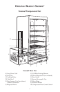
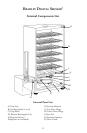
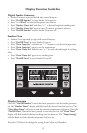
Set Up Smoker Tower:
• Place Racks, either four or six (B)
onto side supports.
• Place Drip Tray (A) “V” facing
down beneath the Racks on the
brass side pins (I).
Place the Rectangular Tray (D) on
the bottom of the Smoker.
• Fill the Drip Bowl (C) half full
with water and place in the center
of Rectangular Tray to catch burnt
Bisquettes. During a long smoking
period, the Drip Bowl will require
changing the water.
• Plug the Long Power Cord (3)
from the Smoke Generator into an
approved grounded electrical outlet
(4). (see page 12)
To Remove Smoke Generator (see page 12)
• Make sure the Smoke Generator
has had time to cool down. Unplug
Long Power Cord from the wall
outlet (4) and from the Smoke
Generator (3). Detach Sensor Cable
(1) and Short Jumper Cord (2)
and then remove Smoke Generator
from the Smoker Tower by raising
it gently upward and pulling it
outward.
As s e m b l y In s t r u c t I o n s
4 Rack Digital Smoker (Model: BTDS76P; BTDS76CE-EU)
6 Rack Digital Smokers (Model: BTDS108P; BTDS108CE-EU)
For Original Black Smoker and Stainless Steel Smoker Assembly Instructions See Page 5
Refer to Part Numbers in External Components List, Internal Components List and Electrical
Connection Set Up
9