


Special offers from our partners!

Find Replacement BBQ Parts for 20,308 Models. Repair your BBQ today.

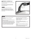
MAINTENANCE
Note: The factory setting of the Default Temperature is
at a position of even amounts of hot and cold water
flows. This setting can only be changed within the first
15 minutes of switching on the power.
1. Remove the power to the faucet by unplugging the
Power Supply from the wall outlet. Wait 60 seconds, and
then plug the Power Supply Back into the wall outlet.
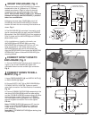
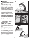
2 . Place hand in front of Blue (Cold) Sensor until the
Blue LED lights up. Fig. 3.
3. Within the next 5 seconds, start the faucet water flow
by placing hand within the On/Off Sensor range. Fig. 3.
4. Adjust the output faucet temperature by using the
Red (Hot) Sensor to increase, or Blue (Cold) Sensor to
decrease. During this process always keep your hand
within The On/Off Sensor range in order to feel the
change water temperature. Fig. 3, Fig. 3a.
5. Once desired temperature has been set, remove
hands away from the range of sensors. Water flow will
stop and both Red and Blue sensors will light-up for 2
seconds indicating the default temperature has been set.
6. The Default Temperature has been set. This will
remain the default setting untill the setting is changed
again. If power is lost, this will remain the default
setting.
Note: The Default Setting is actually a mechanical
positioning of a mixing valve. Changes in the
supply temperatures will create changes to the
Default Temperature.
HOW TO SET DEFAULT
TEMPERATURE Fig. 3
Fig. 2
3
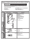
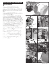
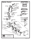
1. Remove four screws and pull off ENCLOUSURE
COVER (1). Fig. 1.
2. Remove MOTOR GEAR COVER (2) by pulling off or
pry off with a flat-blade screw driver. Fig. 1a.
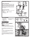
3. Remove SCREW (3) from the center of the LARGE
GEAR (4) and two SCREWS (5) from the MOTOR
HOUSING (6). Fig. 1a.
4. Pull of MOTOR HOUSING (6) with LARGE GEAR
(4) from the MIXING VALVE STEM (7). Fig. 1b.
5. Remove LOCKNUT (8) from the MIXING VALVE
HOUSING (9) using adjustable wrench. Fig. 1c.
6. Pull out MIXING VALVE (10). Use pliers if necessary.
Fig. 1d.
7. Reverse above steps for assembly.
HOW TO REMOVE MIXING
VALVE Fig. 1
1
Fig. 1
5
1
2
6
6
8
9
10
7
4
3
Fig. 1a
Fig. 1b
Fig. 1c
Fig. 1d
Fig. 3
ADJUST HOT
BLUEBLUE
SENSORSENSOR
RED SENSORRED SENSOR
ADJUST
COLD
6
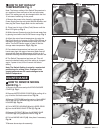
Fig. 3a
BLUE
SENSOR
RED SENSOR
REMOVE
INSTALL
M968857 REV.1.2