


Special offers from our partners!

Find Replacement BBQ Parts for 20,308 Models. Repair your BBQ today.
Page 6
$'9,6(7+$7
:
The curing effect of heating the coals will cause an initial odour, which although not harmful, may require additional
ventilation until the odour has disappeared.
Any debris or soot is cleaned from the appliance. Advise the customer that they should read their Users Instructions before
operating the fire and always follow the advice in the section headed ‘Removal of Debris or Soot Deposits’.
The appliance must be serviced annually by a competent person; i.e. a CORGI registered installer in accordance with these
instructions and that the appliance is checked for spillage in accordance with the method detailed in these instructions.
The appliance is fitted with an Oxy-pilot to prevent the continued operation in the event of spillage occurring. If the fire
shuts ‘OFF’ repeatedly the appliance must be turned off and not used until an expert is consulted. The Oxy-pilot must not
be adjusted or rendered inoperable and replacements must only be the manufacturers supplied part.
Complete the section in the enclosed registration leaflet. Advise that any component or part of this appliance is guaranteed
against defective workmanship or faulty materials for a period of twelve months from the date of purchase.
Any such part will be replaced free of charge on receipt of the purchasers address at the cost of postage only, provided
that:
a)
It is accompanied by the registration section cut out of the booklet together with the original purchase receipt, which
will be returned with the replacement part.
b)
A competent person has carried out installation repairs or adjustments, such as the supplier’s representative or a
CORGI registered installer.
0$,17(1$1&($1'6(59,&,1*
GENERAL
A.
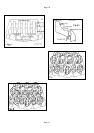
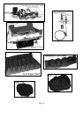
REMOVAL OF DEBRIS OR SOOT DEPOSITS;
Allow the appliance to cool for one hour before removing all the coals and coal bed components for cleaning purposes. Once
all the components have been removed from the fire bed check that no debris has become lodged in the burner port. If any
debris is present it may be easily removed with a thin piece of card or similar to ease out any foreign matter. To ensure that
the release of fibres from these RCF articles is kept to a minimum, during installation and servicing we recommend that
you use a HEPA filtered vacuum to remove any dust and soot accumulated in and around the fire before and after
working on the fire. When replacing these articles we recommend that the replaced items are not broken up, but are
sealed within heavy duty polythene bags, clearly labelled as RCF waste. This is not classified as "hazardous waste" and
may be disposed of at a tipping site licensed for the disposal of industrial waste. Protective clothing is not required when
handling these articles, but we recommend you follow the normal hygiene rules of not smoking, eating or drinking in the
work area and always wash your hands before eating or drinking. Any soot deposits may be removed from either the
Thermocouple or Electrode tips with a soft cloth, do not use abrasive materials.
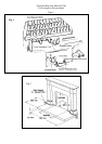
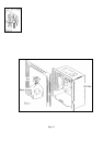
B. SERVICING COMPONENTS BELOW THE BURNER ASSEMBLY
Remove trim (held in place by magnets). Remove the coals, coal support and front simulated coal. To gain access to the
components below the burner assembly it has to be removed from the Vent Box by disconnecting the gas supply at the inlet
elbow and unscrewing the two screws at the base of the fascia panel. Lift the assembly approximately 20mm at the front to
clear the fixing flange. When refitting observe that the two feet at the rear of the assembly locate under the two lugs formed
in the base of the box assembly.
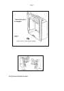
i) TO CLEAN OR REPLACE THE INJECTOR: Unscrew the compression nut connecting the gas supply to the injector
elbow while supporting the injector to prevent any distortion of the frame work. Unscrew and remove the gas supply tube
from the gas control valve, hold the injector lock nut with a spanner and rotate the injector. Replace in the reverse order.
ii) TO REPLACE THE GAS CONTROL / FSD: Disconnect the three gas pipes and the thermocouple from the control. .
Pull the control knob from the spindle; undo the two screws securing the control bracket to the main assembly. The tap
may now be withdrawn. Replace in the reverse order.