


Special offers from our partners!

Find Replacement BBQ Parts for 20,308 Models. Repair your BBQ today.
Page 4
,167$//,1*7+($33/,$1&(
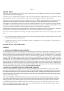
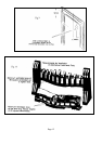
If a fire back (chair brick) is fitted in the existing builders
opening (constructed of non-combustible material)
it will
be necessary to remove it together with any infill or rubble. Any remedial work should be carried out including
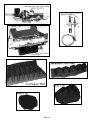
levelling the base beneath the fire. The sizes required for the opening are shown in Fig 2.
',60$17/,1*7+(),5(35,2572,167$//,1*
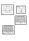
To prevent any damage and to assist with the installation of the appliance both the burner and the trim should be
removed. The trim is held in place by magnets. To remove the burner from the box unscrew the two screws at the
base of the fascia panel and lift the assembly approximately 200mm at the front to clear the fixing flange. When
refitting observe that the two feet at the rear of the assembly locate under the two lugs formed in the base of the
box assembly.
*$66833/<
BEFORE COMMENCING WORK, TURN OFF ANY APPLIANCES THAT ARE FED BY THE METER
AND ISOLATE THE SUPPLY BY TURNING OFF AT THE METER.
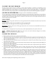
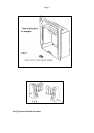
The gas connection to this appliance is made with 8mm O/D rigid or semi rigid tube to a combined pressure
test/restrictor elbow situated on the right-hand side of the burner as shown in Fig 1. Any pipe used under the tray
must be rigid tube such as bundy, a length is supplied for the convenience of the installer. Provision is made in the
rear of the box to make a concealed connection; (additional holes may be drilled as required). The installer is
reminded of the requirements of BS 6891 1988 dealing with enclosed pipes. The standard requires that when a gas
pipe is fed through a wall, the pipe should be enclosed in a tight sleeve to protect against failure caused by
movement and shall be constructed to prevent a passage of gas either between the pipe and sleeve or sleeve and the
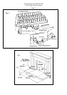
wall. If a gas supply is required to be fed from either the left or right across the front of the appliance it should be
routed as shown in Fig 2. It is only the MACH II Front & Fret that has provision for this requirement alternative
Fronts & Frets will need modifying to allow access for the supply tube, see Fig 4.
),77,1*7+(9(17%2;
.
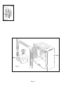
Position the box in the centre of the opening it is secured in place with the two 10x11/4 round headed screws and
plastic plugs supplied in the fitting kit using the two holes in the base of box. Replace the burner assembly in
position ensuring that the rear legs locate under the tags in the base plate and secure with the two screws provided.
Complete the gas connection to the burner as required and fit the trim (held in place by magnets), if the brass trim
is used remove the protective plastic coating before lighting fire.
72&+(&.7+($33/,$1&(6(77,1*35(6685(/($.7(67
A Pressure Test Point at the inlet elbow enables verification of the inlet pressure of the appliance under operating
conditions and can also be used to check the gas soundness of the connections to the appliance gas control. To
check the joints of the burner assembly for gas soundness it will be necessary to carry out the examination prior to
installing into the case. If a manometer is used care must be taken to ensure that it is not disconnected with the gas
turned on and the fuel bed hot.