


Special offers from our partners!

Find Replacement BBQ Parts for 20,308 Models. Repair your BBQ today.

Page 5
729(5,)<7+(,1/(735(6685(
The inlet pressure should be observed at 20mbar +/- 1mbar when the appliance is operating at its maximum rate. Any
significant reduction below an inlet pressure of 20mbar will indicate a restriction in the gas supply to the appliance that
should be identified and corrected. If there are any other appliances, which are relatively high rated (e.g., a central heating
boiler), fed from the same gas supply branch, it is advisable to perform this observation with both appliances in operation.
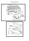
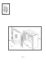
/2&$7,212)7+(),%5(%('
(See pages 14 & 15 for identification of components)
The coal support shelf is positioned on the fibre support metalwork, ensure that the shelf sits against the two stops which are
to prevent the shelf sitting on the burner outlet. Place the simulated coal front in the position shown in Fig 6, three tabs are
provided to locate. The one-piece support shelf is constructed to allow three levels of coal support; these three levels are
shown in Fig 6, the plan view of the bed.
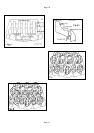
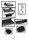
&2$//$<287
First Layer. Position 3 large and 6 small coals across the gap between the front simulated coal and the lower level of the
coal support shelf.
Position 4 large and 3 small coals on the middle level of the coal support shelf.
Position 3 large coals on the upper level of the coal support shelf. See figure 7.
Second Layer. Position 6 small coals to fill the gaps between the coals on the lower level and middle level of the coal
support shelf. See figure 8.
To obtain the best visual appearance it may be necessary to make slight adjustments to the position of the coals.
NOTE: Additional coals must not be used. If any of the coals or the coal bed becomes damaged, lost or broken,
replacements must be obtained before the appliance is used
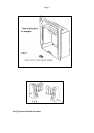
72/,*+77+($33/,$1&(
1.
Remove the fret (controls cover), to gain access to the controls.
2.
Press and turn the gas control anti-clockwise, keep the control fully depressed to purge the air from the pipework. Turn
‘OFF’ and repeat the operation, check that a spark occurs between the electrode and the head of the pilot. The pilot will
light, if not repeat the operation.
3.
0nce a pilot-flame has been established; keep the control depressed for a further 20 seconds. Release the gas control and
check that the pilot remains lit.
4.
Depress the gas control slightly and turn anti-clockwise until the indicator mark is aligned with the letters HIGH. The
burner will cross light from the pilot.
5.
Depress the gas control slightly and turn anti-clockwise until the indictor mark is aligned with the letters LOW The
burner will now be at minimum rate.
6.
Turn the gas control to the OFF position, wait for 3 minutes, fully depress the gas control, turn to IGN position and
release the control. Attempt to ignite the pilot with an already lighted match or taper. If the pilot ignites the FSD is
faulty.
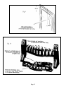
7.
Re-light the appliance. With the control set to the maximum rate (large flame) position, place the Fire front & fret in
position and leave to heat up for 5 minutes. Check for satisfactory clearance of products by inserting a lighted smoke
match into the opening in the position shown in Fig 10, i.e. 100mm below the top, and 40mm inside of the front face of
the opening, all the smoke must be drawn into the flue. If spillage occurs, allow a further 10 minutes. Should spillage
still occur examine the chimney for the fault and rectify the cause. The test should be repeated if an extractor fan is
situated in the room, or in any connecting room, with all the doors in that room opened.
Demonstrate the lighting and extinguishing procedures to the user.