


Special offers from our partners!

Find Replacement BBQ Parts for 20,308 Models. Repair your BBQ today.

6
W415-0381 / H / 12.07.07
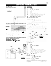
A terminal shall not terminate directly above a sidewalk or paved
driveway which is located between two single family dwellings
and serves both dwellings. Local codes or regulations may
require different clearances.
Do not allow the inside liner to bunch up on horizontal or ver-
tical runs and elbows. Keep it pulled tight. A 1¼" air gap all
around between the inner liner and outer liner is required for
safe operation. Use a firestop when penetrating interior walls,
floor or ceiling.
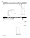
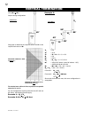
*HORIZONTAL VENT SECTIONS: A minimum clearance of 2" all
around the vent pipe on all horizontal runs to combustibles is required.
Use fi restop spacer W010-1778 (supplied).
VERTICAL VENT SECTIONS: A minimum of 1" all around the vent
pipe on all vertical runs to combustibles is required except for clear-
ances in fi replace enclosures. Use fi restop spacer W500-0367 (not
supplied).
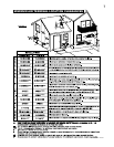
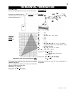
Horizontal runs may have a 0" rise per foot in all cases using
SIMPSON DURA-VENT, SELKIRK DIRECT TEMP, AMERICAN
METAL AMERIVENT or NAPOLEON RIGID OR FLEXIBLE venting
components when venting as illustrated in Figures 3, and 4.
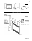
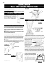
Minimum clearance to combustible con-
struction from fireplace and vent sur-
faces:
Sides, back, bottom and 0"
top of the unit
Recessed depth 22"
All around the vent pipe* 2"
Enclosure top 45 1/2"
Ceiling 72" from bottom of unit
For optimum performance it is recommended that all horizontal
runs have a 1" rise per foot when using Napoleon® flexible vent
components.
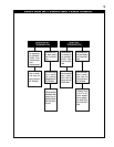
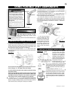
These vent kits allow for either horizontal or vertical venting of the
fi replace. FIGURES 3 & 5. The maximum allowable horizontal run is
20 feet. The maximum allowable vertical vent length is 40 feet. The
maximum number of 5" vent
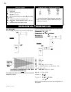
VENTING
Use only Wolf Steel, Simpson Dura-Vent, Selkirk Direct Temp or
American Metal Amerivent venting components. Minimum and
maximum vent lengths, for both horizontal and vertical installations,
and air terminal locations for either system are set out in this manual
and must be adhered to. For Simpson Dura-Vent, Selkirk Direct Temp
and American Metal Amerivent, follow the installation procedure
provided with the venting components.
All outer pipe joints of these venting systems must be sealed using
Red RTV Hight Temperature Sealant.
Wolf Steel, Simpson Dura-Vent, Selkirk Direct Temp and American
Metal Amerivent venting systems must not be combined.
A starter adaptor must be used and may be purchased from the cor-
responding supplier:
Supplier 4&7 ZC 5&8 ZC GAS STOVE
Dura-Vent W175-0053 W175-0170 GDS924N
Amerivent 4DSC-N2 5DSC-N 4DSCB-N1
Direct Temp 4DT-AAN 5DT-AA 4DT-AAN
VENTING LENGTHS
For Simpon Dura-Vent, Selkirk Direct Temp and American Metal
Amerivent, follow the installation procedure found on the website for
your venting supplier:
VENTING SUPPLIER WEBSITE ADDRESS
Simpson Dura-Vent www.duravent.com
Selkirk Direct Temp www.selkirkcorp.com
American Metal Amerivent www.americanmetalproducts.com
For vent systems that provide seals on the inner exhaust fl ue, only the
outer air intake joints must be sealed using a red high temperature
silicone (RTV). This same sealant maybe used on both the inner
exhaust and outer intake vent pipe joints of all other approved vent
systems except for the exhaust vent pipe connection to the fi replace
fl ue collar which must be sealed using the black high temperature
sealant W573-0007 (not supplied) Mill Pac.
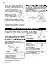
When using Wolf Steel venting components, use only approved Wolf
Steel rigid / fl exible components with the following termination kits:
WALL TERMINAL KIT GD422, or 1/12 TO 7/12 PITCH ROOF TER-
MINAL KIT GD410, 8/12 TO 12/12 ROOF TERMINAL KIT GD411,
FLAT ROOF TERMINAL KIT GD412 or PERISCOPE KIT GD401 (for
wall penetration below grade). With fl exible venting, in conjunction
with the various terminations, use either the 5 foot vent kit GD420 or
the 10 foot vent kit GD430.
The air terminal must remain unobstructed at all times. Examine
the air terminal at least once a year to verify that it is unob-
structed and undamaged.
Purge all gas lines with the glass door of the fireplace removed.
Assure that a continuous gas flow is at the burner before re-
installing the door.
Under extreme vent configurations, allow several minutes (5-15)
for the flame to stabilize after ignition.