


Special offers from our partners!

Find Replacement BBQ Parts for 20,308 Models. Repair your BBQ today.

17
W415-0381 / H / 12.07.07
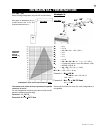
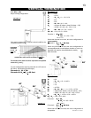
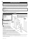
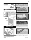
1. Move the fi replace into position.
2. Fasten the roof support to the roof using the screws provided.
FIGURE 21. The roof support is optional. In this case the venting is
to be adequately supported using either an alternate method suitable
to the authority having jurisdiction or the optional roof support.
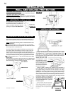
3. Apply high temperature sealant W573-0007 (not supplied)
to the outer edge of the inner sleeve of the air terminal. Slip a 5"
diameter coupler a minimum of 2" over the sleeve and secure using
3 screws.
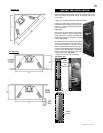
4. Apply high temperature sealant
W573-0007 (not supplied) to the outer
edge of the of the outside sleeve of the
air terminal. Slip a 8" diameter coupler
over the sleeve and secure as before.
FIGURE 25. Trim the 8" coupler even
with the 5" coupler end.
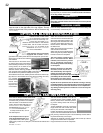
5. Thread the air terminal pipe as-
sembly down through the roof support
and attach, ensuring that a minimum
16" of air terminal will penetrate the
roof when fastened. FIGURE 23. If
the attic space is tight, we recom-
mend threading the Wolf Steel vent
pipe collar or equivalent loosely
onto the air terminal assembly
as it is passed through the attic.
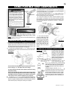
FIGURE 29. The air terminal must be
located vertically and plumb.
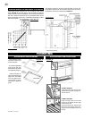
6. Remove nails from the shingles,
above and to the sides of the chim-
ney. Place the fl ashing over the air
terminal and slide it underneath the
sides and upper edge of the shingles. Ensure that the air terminal
is properly centered within the fl ashing, giving a 3/4" margin all
around. Fasten to the roof. Do NOT nail through the lower portion
of the fl ashing. Make weather-tight by sealing with caulking. Where
possible, cover the sides and top edges of the fl ashing with roofi ng
material. FIGURE 23.
7. Aligning the seams of the terminal and air terminal connector,
place the terminal over the air terminal connector making sure the
inner sleeve goes into the hole in the terminal. Secure with the 3
screws provided.
8. Apply a heavy bead of weatherproof caulking 2" above the
fl ashing. Note: Maintain a minimum of 2" space between the air
inlet base and the storm collar. Install the storm collar around the
air terminal and slide down to the caulking. Tighten to ensure that
a weather-tight seal between the air terminal and the collar is
achieved.
9. Continue adding rigid venting sections, sealing and securing
as above. Attach a 5" collapsed telescopic pipe to the last section
of rigid piping. Secure with screws and seal. Repeat using a 8"
telescopic pipe.
10. Run a bead of high temperature sealant W573-0007 (not sup-
plied) Mill Pac around the outside of the 5" collar on the fi replace.
Pull the adjustable pipe a minimum of 2" onto the collar. Secure with
3 screws. Repeat with the 8" telescopic pipe.
11. In the attic, slide the vent pipe collar down to cover up the open
end of the shield and tighten. This will prevent any materials, such as
insulation, from fi lling up the 1" air space around the pipe.
FIGURE 30
FIGURE 29
FIGURE 32
VERTICAL VENTING INSTALLATION
GAS INSTALLATION
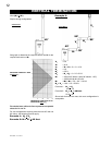
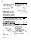
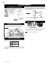
RESTRICTING VERTICAL VENTS
RESTRICTOR PLATE
TOP OF THE
FIREBOX
FIGURE 31
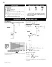
For ease of accessibility, an optional remote wall switch may be
installed in a convenient location.
A 20’ length of millivolt wire is
connected to the gas valve for the wall switch. However if a greater
length is required
route 2-strand (solid core) millivolt wire through the
electrical hole located at the bottom left side of the unit. The recom-
mended maximum lead length depends on wire size:
WIRE SIZE MAX. LENGTH
14 gauge 100 feet
16 gauge 60 feet
18 gauge 40 feet
Attach the two leads to terminals 1 and 3 located on the gas valve.
OPTIONAL WALL SWITCH
INSTALLATION
Vertical terminations may display a very active fl ame. As this appear-
ance is not desirable, the vent exit must be restricted using restrictor
plate, W500-0205. This reduces the velocity of the exhaust gases,
slowing down the fl ame pattern and creating a more traditional ap-
pearance.
Remove the two screws on either side of the exhaust collar inside the
fi rebox. Install the plate as shown. Replace the screws.
Proceed once the vent installation is complete.
NOTE: All gas connections must be contained within the fi re-
place when complete.
1. Move the fi replace into position and secure to the fl oor through
the 1/4" holes located at either side of the base.
2. The fi replace is designed to accept 3/8" gas supply line. The
fi replace is equipped with a 3/8" manual shut-off valve.
3. Connect the gas supply in accordance to local codes. In the
absence thereof, install according to the National Installation Code.
4. When fl exing any gas line, support the gas valve so that the
lines are not bent or kinked.
5. Check for gas leaks by brushing on a soap and water solu-
tion.
DO NOT USE OPEN FLAME.
Purge all gas lines with the glass door of the stove removed.
Assure that a continuous gas fl ow is at the burner before re-
installing the door.