


Special offers from our partners!

Find Replacement BBQ Parts for 20,308 Models. Repair your BBQ today.

15
W415-0381 / H / 12.07.07
DO NOT CLAMP
THE FLEXIBLE
LINER
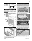
FIGURE 24b
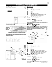
1. Fasten the roof support
to the roof using the screws
provided. The roof support
is optional. In this case the
venting is to be adequately
supported using either an al-
ternate method suitable to the
authority having jurisdiction or
the optional roof support.
2. Stretch the inner
vent pipe
to the required length. Slip
the
vent pipe a minimum of 2” over the inner
sleeve of the air terminal connector and secure
with 3 #8 screws. Seal using a heavy bead of
the high temperature sealant W573-0007 (not
supplied).
3. Repeat using the outer fl ex
vent pipe.
4. Thread the air terminal connector / liner as-
sembly down through the roof. The air terminal
must be located vertically and plumb. Attach
the air terminal connector to the roof support,
ensuring that the top of the air terminal is 16”
above the highest point that it penetrates the
roof.
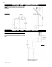
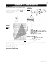
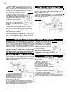
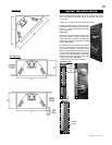
FIGURE 20
1. Stretch the 5" diameter fl exible vent pipe to the required length
taking into account the additional length needed for the fi nished wall
surface. Slip the liner a minimum of 2" over the inner sleeve of the
air terminal and secure with 3 #8 screws. Apply a heavy bead of the
high temperature sealant (W573-0007 not supplied).
2. Using the 8" diameter fl exible
vent pipe, slide over the outer
combustion air sleeve of the air terminal and secure with 3 #8 screws.
Seal as before.
The air terminal mounting plate may be recessed into the exterior
wall or siding by 1½", the depth of the return fl ange.
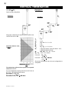
4. Apply a heavy bead of the high temperature sealant W573-0007
(not supplied), Mill Pac, to the inside of the 5"
vent pipe approximately
1" from the end. Slip the
vent pipe a minimum of 2" over the fi replace
vent collar and secure with 3 #8 screws.
5. Using the 8" diameter fl exible
vent pipe, apply sealant W573-
0002 (not supplied), slide a minimum of 2" over the fi replace combus-
tion air collar and secure with 3 #8 screws.
6. If more liner needs to be used to reach the fi replace, couple
them together as illustrated. The vent system must be supported
approximately every 3 feet for both vertical and horizontal runs. Use
noncombustible strapping to maintain the minimum 1" clearance to
combustibles.
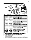
7. The vent heat shield
must be installed only when
terminating horizontally. Re-
move the two screws nearest
the vent collars on the top of
the fi replace. Align the vent
heat shield (supplied) and
secure. Adjust the vent heat
shield to touch the firestop
spacer.
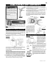
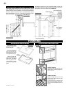
FIGURE 21
HORIZONTAL AIR TERMINAL INSTALLATION
VERTICAL AIR TERMINAL INSTALLATION
FIGURE 22
Use only approved flexible vent pipe kits marked:
"Wolf Steel Approved Venting" as iden-
tified by the stamp only on the 7” outer
vent pipe.
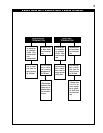
USING FLEXIBLE VENT COMPONENTS
For safe and proper operation of the fireplace, follow the venting
instructions exactly.
All inner exhaust and outer intake vent pipe joints may be sealed
using either Red RTV high temp silicone sealant or Black high
temp Mill Pac with the exception of the fireplace exhaust flue
collar which must be sealed using Mill Pac (not supplied).
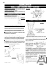
3. Insert the
vent pipe assemblies through the fi restop maintaining
the required clearance to combustibles. Holding the air terminal (let-
tering in an upright, readable position), secure to the exterior wall and
make weather tight by sealing with caulking (not supplied).
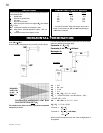
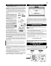
FIGURE 23
Do not allow the inside vent pipe to
bunch up on horizontal or vertical
runs and elbows. Keep it pulled tight.
A 1 1/4" air gap between the liner and
outer liner all around is required for
safe operation. A spacer is required
at the start, middle and end of each
elbow to ensure this gap is maintained.
See Figure 20.
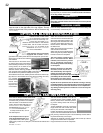
Spacers are attached to the inner fl ex
liner at predetermined intervals to
maintain a 1 1/4" air gap to the outer
fl ex pipe. These spacers must not be
removed.
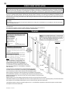
FIGURE 24a
NOTE: Eight (8") inches is the minimum bend radius allowed for the
8" diameter fl exible vent pipe.
!
WARNING
ELBOWS
SPACERS