


Special offers from our partners!

Find Replacement BBQ Parts for 20,308 Models. Repair your BBQ today.

22
W415-0381 / H / 12.07.07
FIGURE 44
FIGURE 48
FIGURE 49
FIGURE 45
FIGURE 50
INSTALLATION TO BE DONE
BY A QUALIFIED INSTALLER
and must be electrically con-
nected and grounded in ac-
cordance with local codes. In the absence
of local codes, use the current CSA C22.1
CANADIAN ELECTRICAL CODE in Canada or the
ANSI/NFPA 70 NATIONAL ELECTRICAL
CODE in the United States
If the fi replace was not previously
equipped with a blower: route a
grounded 2-wire, 60hz power cable to the receptacle / junction box.
At this point, it must be strain relieved
and insulated.
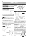
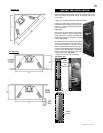
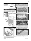
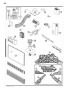
The three slots on the blower mount-
ing bracket allow ease of adjustment
when attaching the blower. For a quiet
running blower, do not allow the as-
sembly to sit on the fi rebox base.
Slide the vibration reducing pad (A) into the clip (C)
and up against the threaded stud (B) at the other end. The blower
must be able to be positioned entirely onto the pad.
Tilt the blower onto its side. Slide it past the controls and into the clip
(C). Secure to the threaded stud using the lock washer and wing
nut provided.
Ensure that the
blower does
not touch the
fi replace base
or the fi rebox.
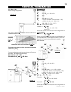
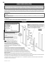
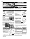
5. Place the bottom of the right crossover log (W135-0302)
onto the stud on the right side of the log support. The top
of the log should rest in the pocket on the left crossover log
(W135-0300).
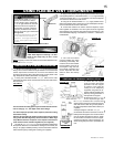
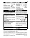
Attach the connectors from the black
and white wires to the thermodisc and
secure the thermodisc bracket to the
securing stud at the bottom left of the
unit using a lock washer and wing nut.
Ensure that the thermodisc touches
the fi rebox wall.
Attach the connectors from the black
and red wires to the blower.
Attach and secure the variable speed
switch using the nut provided. Plug the
harness cord into the receptacle.
The wire harness provided in this
kit is a universal harness. When
installed, ensure that any excess
wire is contained, preventing it
from making contact with moving
or hot objects.
Because the blower is thermally
activated, when turned on, it
will automatically start approxi-
mately 10 minutes after lighting
the fireplace and will run for ap-
proximately 30-45 minutes after
the fireplace has been turned
off. Use of the fan increases the output of heat.
Drywall dust will penetrate into the blower bearings, causing
irreparable damage. Care must be taken to prevent drywall dust
from coming into contact with the blower or its compartment.
Any damage resulting from this condition is not covered by the
warranty policy.
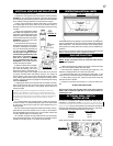
CHARCOAL EMBERS
VERMICULITE
CHARCOAL LUMPS
OPTIONAL BLOWER INSTALLATION
Randomly place the charcoal embers along the front and sides of the
log support tray in a realistic manner. Fine dust found in the bottom
of the bag should not be used.
Sprinkle vermiculite around the charcoal embers.
Note: Both charcoal embers and vermiculite are not to be placed
on the burner.
Place the lumps between the logs in a realistic manner taking care
not to block any of the burner ports.
C
A
B
FIGURE 46
FIGURE 47
ELECTRICAL INSTALLATION TO BE DONE
BY A QUALIFIED INSTALLER and must be
connected and grounded in accordance
with local codes. In the absence of local
codes, use the current CSA C22.1 CA-
NADIAN ELECTRICAL CODE in Canada or
the ANSI/NFPA 70 NATIONAL ELECTRI-
CAL CODE in the United States.
To safely install the fan, turn off
the electricity fi rst.
If the fi replace was not previ-
ously equipped with a fan: route
a grounded 2-wire, 60hz power
cable to the junction box. At this point, it must be strain relieved and
insulated.
The wire harness provided in this kit is a
universal harness. When installed, ensure
that any excess wire is contained, prevent-
ing it from making contact with moving or
hot objects.
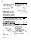
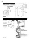
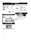
To ease installation of the fan, remove the
hinge screen and valve control door (lower
louvres) from the base of the fi replace.
Position the vibration reducing pad into the
clip and onto the threaded stud at the other
end, piercing a hole into the pad. The fan assembly must be able to
be positioned entirely onto the pad.
Slide the fan assembly past the controls and into the clip. Secure
using the lock washer and nut provided.
Plug the harness cord into the receptacle.
OPTIONAL FAN INSTALLATION
FIGURE 51