


Special offers from our partners!

Find Replacement BBQ Parts for 20,308 Models. Repair your BBQ today.

14
W415-0381 / H / 12.07.07
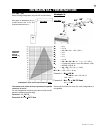
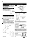
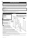
1. Determine the air terminal location, cut and frame 10 3/4" square
openings in the ceiling and the roof to provide the minimum 1" clear-
ance between the vent pipe and any combustible material. Try to
center the vent pipe location midway between two joist to prevent
having to cut them. Use a plumb bob to line up the center of the open-
ings. DO NOT FILL THIS
SPACE WITH ANY TYPE
OF MATERIAL. A vent
pipe shield will prevent any
materials such as insula-
tion, from fi lling up the 1"
air space around the pipe.
Nail headers between the
joist for extra support.
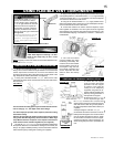
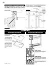
2. Apply a bead of caulking (not supplied) to the framework or
to the Wolf Steel vent pipe shield plate or equivalent (in the case
of a fi nished ceiling), and secure over the opening in the ceiling.
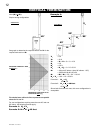
FIGURE 18. A fi restop must be placed on the bottom of each framed
opening in a roof or ceiling that the venting system passes through.
Apply a bead of caulking all around and place a fi restop spacer over
the vent shield to restrict cold air from being drawn into the room or
around the fi replace. Ensure that both spacer and shield maintain
the required clearance to combustibles.
Once the vent pipe / liner is installed in its
fi nal position, apply sealant W573-0002
(not supplied) between the
vent pipe and
the fi restop spacer.
3. In the attic, slide the vent pipe
collar down to cover up the open end
of the shield and tighten. This will pre-
vent any materials, such as insulation,
from fi lling up the 1" air space around
the pipe.
FIGURE 17
FIGURE 16a
FIGURE 15
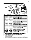
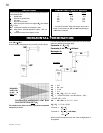
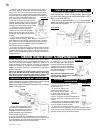
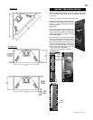
HORIZONTAL VENT SECTIONS: A minimum clearance of 2" all
around the vent pipe on all horizontal runs to combustibles is required.
Use fi restop spacer W010-1778 (supplied).
VERTICAL VENT SECTIONS: A minimum of 1" all around the vent
pipe on all vertical runs to combustibles is required. Use fi restop
spacer W500-0367 (not supplied).
HORIZONTAL INSTALLATION
VERTICAL INSTALLATION
INSTALLATION
WALL AND CEILING PROTECTION
FIGURE 18
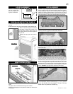
FIGURE 16b
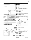
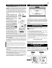
This application occurs when venting
through an exterior wall. Having determined
the air terminal location, cut and frame a
hole in an exterior wall with a minimum
opening as required. See Note above.
Apply a bead of caulking all around and place the fi restop top, so
that the vent shield covers the top of the vent within the opening.
NOTE: The fi restop assembly must be installed with the vent
shield to the top.
The length of the vent shield may be cut shorter for combustible
walls that are less than 8 1/2" thick but the vent shield must extend
the full depth of the combustible wall.
Place the fi restop bottom against the fi restop top and secure the
two together. Adjust the assembly to ensure it is tight to the vent.
Secure fi restop to wall. This restricts cold air from being drawn
into the room or around the fi replace. Ensure that both spacer and
shield maintain the required clearance to combustibles. Once the
vent pipe is installed in its fi nal position, apply sealant W573-0002
(not supplied) between the vent pipe and the fi restop spacer. See
fi gures 16a-c.
This application occurs when venting through a roof. Installation kits
for various roof pitches are available from your Napoleon® dealer.
See Accessories to order the specifi c kit required.
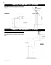
ADJUSTABLE FIRESTOP INSTALLATION
FIRESTOP TOP
FIRESTOP BOTTOM
VENT SHIELD
FIGURE 16c
VENT PIPE
SHIELD
VENT
PIPE
CO LLAR
FIGURE 19