


Special offers from our partners!

Find Replacement BBQ Parts for 20,308 Models. Repair your BBQ today.

22
W415-0381 / E / 02.09.06
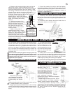
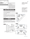
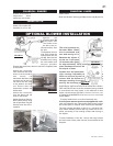
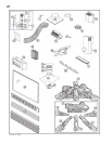
Position the vibration reducing pad into the clip and onto
the threaded stud at the other end, piercing a hole into the
pad. The fan assembly must be able to be positioned en-
tirely onto the pad.
Slide the fan assembly past the controls and into the clip.
Secure using the lock washer and nut provided.
After extended periods of non-operation such as following
a vacation or a warm weather season, the fireplace may
emit a slight odour for a few hours. This is caused by dust
particles in the heat exchanger burning off. In both cases,
open a window to sufficiently ventilate the room.
Purge the gas line with the glass door removed. As-
sure that a continuous gas flow is at the burner before
re-installing the door.
A. This fireplace is equipped with a pilot which must be lit
by hand while following these instructions exactly.
B. Before operating smell all around the fireplace area for
gas and next to the floor because some gas is heavier
When installed, ensure that any excess wire is contained,
preventing it from making contact with moving or hot ob-
jects.
When lit for the first time, the fireplace will emit a slight
odour for a few hours. This is a normal temporary condi-
tion caused by the curing of the logs and the "burn-in" of
internal paints and lubricants used in the manufacturing
process and will not occur again.
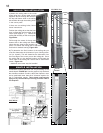
Plug the harness cord into the receptacle.
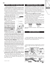
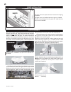
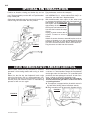
This optional kit is meant to be used only in conjunction
with the GD65 Fan Kit, shown above, which may be or-
dered from your Wolf Steel / Napoleon dealer.
With the thermostatic sensor option, the fan, when turned
on, becomes thermally activated, and will automatically run
approximately 15-30 minutes after
the fireplace has been lit and for
approximately 30-45 minutes after
the fireplace has been turned off.
Use of the fan increases the output
of heat.
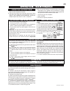
Unplug the power cord from the re-
ceptacle. Connect all wires as
shown.
Attach and secure the sensor assembly bracket to the se-
curing stud located next to the receptacle/junction box at
the bottom left of the unit using the lock washer and wing
nut. Ensure that the thermodisc touches the firebox wall.
Plug the power cord back into the receptacle.
FIGURE 48
FIGURE 47
FIGURE 49
FIGURE 50
OPTIONAL FAN INSTALLATION
GD36 THERMOSTATIC SENSOR CONTROL