


Special offers from our partners!

Find Replacement BBQ Parts for 20,308 Models. Repair your BBQ today.

15
W415-0381 / E / 02.09.06
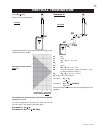
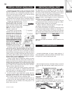
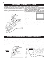
STORM COLLAR
FLASHING
CAULKING
WEATHER
SEALANT
2”
AIR INLET
BASE
FIGURE 25
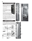
The vent system must be supported approximately every 3
feet for both vertical and horizontal runs. Use Wolf Steel
vent spacers every 3 feet and either side of each elbow to
maintain the minimum 1¼" clearance between the outer
and inner vent pipes. Use Wolf Steel support ring assem-
bly or equivalent noncombustible strapping to maintain the
minimum clearance to combustibles for both vertical and
horizontal runs.
All inner exhaust and outer intake vent pipe joists may
be sealed using either Red RTV high temp silicone seal-
ant or Black high temp Mill Pac with the exception of the
fireplace exhaust flue collar which must be sealed us-
ing Mill Pac (not supplied).
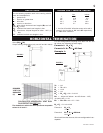
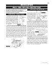
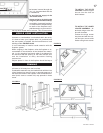
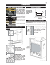
1. Move the fireplace into po-
sition. Measure the vent length
required between terminal and
fireplace taking into account
the
additional length needed for the finished wall surface and any
1¼" overlaps between venting components.
2. Apply high temperature sealant Mill Pac to the outer edge
of the 5" inner collar of the fireplace. Attach the first vent compo-
nent and secure using 3 self tapping screws. Repeat using 8"
piping.
FIGURE 27
3. The heat shield must be
installed only when terminat-
ing horizontally with no verti-
cal rise. Remove the two
screws nearest the vent col-
lars on the top of the fireplace.
Align the vent shield (sup-
plied) and secure.
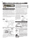
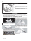
4. Holding the air terminal (with the air deflectors to the
top), insert into both vent pipes with a twisting motion to ensure
that both the terminal sleeves engage into the vent pipes and
sealant. Secure the terminal to the exterior wall and make
weather tight by sealing with caulking (not supplied).
The air terminal mounting plate may be recessed into the
exterior wall or siding by 1½", the depth of the return flange.
1. Follow the instructions for "Horizontal Air Terminal In-
stallations", items 1 to 3.
2. Continue adding compo-
nents alternating inner and
outer venting. Ensure that all 5"
venting and elbows have suffi-
cient vent spacers attached and
each component is securely
fastened to the one prior. Attach the 5" telescopic
sleeve to the vent run.
Repeat using a 8" telescopic sleeve. Secure
and seal as before. To facilitate completion,
attach 5" and 8" couplers to the air terminal.
3. Install the air terminal. See item 3 of the
Horizontal Air Terminal Installation. Extend the 5" telescopic
sleeve; connect to the air terminal assembly. Fasten with
self tapping screws and seal. Repeat using the 8" tel-
escopic sleeve.
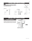
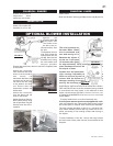
5. Remove nails from the shingles, above and to the
sides of the chimney. Place the flashing over the air
terminal connector leaving a min. 3/4” of the air terminal
connector showing above the top of the flashing. Slide
the flashing underneath the sides and upper edge of the
shingles. Ensure that the air terminal connector is
properly centred within the flashing, giving a 3/4” margin
all around. Fasten to the roof. Do not nail through the
lower portion of the flashing. Make
weather-tight by sealing with caulking.
Where possible, cover the sides and top
edges of the flashing with roofing
material.
6. Aligning the seams of the
terminal and air terminal connector,
place the terminal over the air
terminal connector making sure the
liner goes into the hole in the
terminal. Secure with the three
screws provided.
7. Apply a heavy bead of
weatherproof caulking 2 inches
above the flashing. Note: Maintain a
minimum 2” space between the air
inlet base and the storm collar.
Install the storm collar around the air
terminal and slide down to the caulking. Tighten to
ensure that a weather-tight seal between the air terminal
and the collar is achieved.
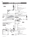
FIGURE 24
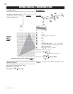
7. If more liner needs to be used to reach the fireplace,
couple them together as illustrated. The vent system must be
supported approximately every 3 feet for both vertical and hori-
zontal runs. Use noncombustible strapping to maintain a
clearance to combustibles of 1".
1. Install the 5 inch diameter aluminium flexible liner to
the fireplace. Secure with 3 screws and flat washers. Seal
the joint and screw holes using the high temperature seal-
ant Mill Pac.
2. Install the 8 inch diameter aluminium flexible liner to
the fireplace. Attach and seal the joints.
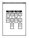
FIREPLACE VENT CONNECTION
USING RIGID VENT COMPONENTS
HORIZONTAL AIR TERMINAL INSTALLATION
EXTENDED HORIZONTAL AIR TERMINAL
INSTALLATION
FIGURE 26
Spacers are
attached to the inner
flex liner at
predetermined
intervals to maintain
a 1-1/4” air gap to
the outer flex liner.
These spacers must
not be removed.