


Special offers from our partners!

Find Replacement BBQ Parts for 20,308 Models. Repair your BBQ today.

5
W415-0369 / E / 02.16.07
INSTALLATION
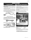
This fi replace is intended for installation on an outdoor patio
or in your yard. It must never be installed inside the warm air
envelope of your structure.
It is highly recommended that this fi replace be installed in a
“sheltered” area. Direct wind will cause an erratic fl ame and
possible pilot or main burner outage.
An erratic fl ame could also lead to excessive carboning
(black soot), this condition is not a safety issue but is visu-
ally undesirable.
Typical installation may include covered patio, screened
porch, gazebo or an outside the wall of a house.*
NOTE: Ensure the area has adequate ventilation.
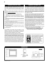
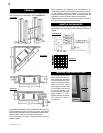
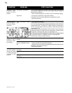
Sides, back, bottom & top 0 inches
Recessed 13¾ inches
Top of unit to ceiling 48”
It is recommended that the walls of the fi replace enclosure be
fi nished. This would ensure that clearance to combustibles
is maintained within the cavity.
COMBUSTION & VENTILATION AIR
CLEARANCE TO COMBUSTIBLES
NOTE: If the unit is installed using a propane cylinder
as a source of fuel, the cylinder must be retained. A
stand for a standard 20lb cylinder is available from your
NAPOLEON® Dealer.
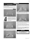
1. Move the fi replace into position and secure using the
nailing tabs and/or secure to the fl oor through the ¼”ø holes
located at either end of the base.
2. Install rigid black pipe, 1/2” type-L copper tubing or, if
local codes permit, a 3/8” fl ex connector and shutoff valve
to the gas line and the fi replace gas valve. Seal and tighten
securely. An adapter fi tting is required between the gas valve
and the copper tubing or fl ex connector.
DO NOT KINK FLEX CONNECTOR.
3. Check for gas leaks by brushing on a soap and water
solution.
DO NOT USE OPEN FLAME.
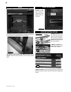
4. For ease of accessibility, an optional remote wall switch
may be installed in a convenient location. Route a 2 strand,
solid core millivolt wire through the electrical hole located at
the bottom left side of the unit. The recommended maximum
lead length depends on wire size:
WIRE SIZE MAX. LENGTH
14gauge 100 feet
16gauge 60 feet
18gauge 40 feet
Attach the two leads to terminals 1 and 3 located on the
gas valve.
Do not connect either the wall switch, thermostat or gas
valve to electricity (110 volts).
FIGURE 3
GAS INSTALLATION
FIGURE 4
* If installing a propane fi replace the propane cylinder
must always be on the exterior of such a structure.
FIGURE 2