


Special offers from our partners!

Find Replacement BBQ Parts for 20,308 Models. Repair your BBQ today.
12
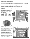
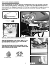
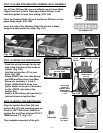
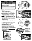
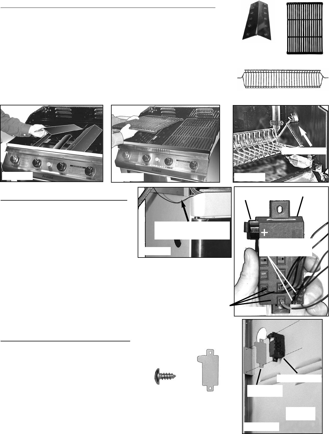
STEP 13) FLAME DIFFUSER/GRID/ WARMING RACK ASSEMBLY:
Lay a Flame Diffuser (54) over each Burner on the lower Body
ridges from front to back. Place each Flame Diffuser in the
individual guides to keep from sliding. (FIG. 13A)
Place the Cooking Grids (55) over the Burner Diffusers on the
upper Body ridges. (FIG. 13B)
Insert the ends of the Warming Rack (56) into the V-shape
hangers at each end of the hood. (Fig. 13C)
Fig. 14B
STEP
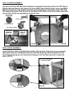
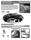
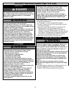
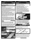
14) WIRING THE IGNITION BOX:
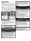
· Route the wiring through the top left
side of the Crossbar to the inside of
cabinet. (Fig. 14A).
· Hold the Ignition Box (57) in your
hand. (Fig. 14B)
· Attach BLACK wire from Side Burner
and RED and Blue wires from Main
Burners to terminals 1, 2 and 3.
· Attach LARGE BLACK wires from
Ignitor Switch to the pair of terminals
on the LOWER right side of the
Ignition Box.
· Install a 9-Volt battery with positive (+)
terminal shown on Ignition Box.
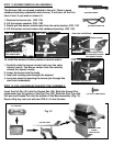
STEP
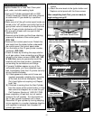
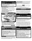
15) INSTALL THE IGNITION BOX:
Align the Ignition Box Shim (58) and
Ignition Box (57) with mounting plate on
inside of LEFT Side Panel. Attach the
Ignition Box and Shim with two ST4.0 X
10MM Screws (13). (Fig. 14C)
This completes assembly of the grill.
Fig. 13A
Fig. 13B
Fig. 13C
V-SHAPE HANGER
(54) FLAME
DIFFUSER
(55) COOKING GRID
(56) WARMING RACK
(57) IGNITION BOX
(58) IGNITION
BOX SHIM
(14/15) LEFT
SIDE PANEL
FIG. 14C
(13) ST4.0 x
10MM SCREW
(58) IGNITION
BOX SHIM
ROUTE WIRING OVER TOP
CORNER OF CROSSBAR ABOVE
THE LEFT DOOR
Fig. 14A
LARGE BLACK WIRES
FROM IGNITOR
BUTTON
1
2
3
9-VOLT
BATTERY
(57) IGNITION BOX
BLACK WIRE
FROM SIDE
BURNER, RED &
GREEN WIRES
TO TERMINALS
1, 2 & 3