


Special offers from our partners!

Find Replacement BBQ Parts for 20,308 Models. Repair your BBQ today.

25
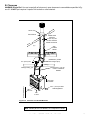
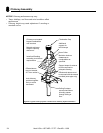
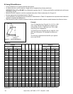
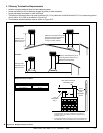
A. Chimney Requirements
Measure vertical distances from the base of the fi replace
as shown in Figure 8.2.
20 ft (6.10 m) max.
pipe between an
offset & return
Ceiling firestop
35 ft (10.67 m) max. straight
unsupported chimney height
16 ft (4.88 m) min. height (single offset-return)
20 ft. (6.10 m) min. height (double offset-return)
90 ft (27.4 m) max. height
6 ft (1.83 m) max.
unsupported chimney
above roof
47-1/4 in.
(1200 mm)
Effective
Height
Figure 8.2 Chimney Requirements
Table 8.1
ft meters
• Minimum overall straight height 14 4.27
• Minimum height with offst/return 16.5 5.03
• Maximum height 90 27.43
• Maximum chimney length bewtween an offset
and return
20 6.10
• Maximum distance between chimney stabilizers 35 10.67
• Double offset/return minimum height 20 6.10
• Maximum unsupported chimney length between
the offset and return
6 1.83
• Maximum unsupported chimney height above the
fi replace
35 10.67
• Maximum unsupported chimney above roof 6 1.83
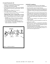
WARNING! Risk of Fire! You must maintain 2 in. (51
mm) air space clearance to insulation and other combus-
tible materials around the chimney system. Failure to do
so may cause overheating and fi re.
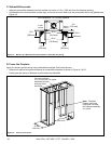
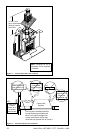
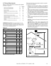
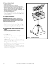
Determine the chimney components needed to complete
your particular installation:
• Measure the total vertical height of the fireplace
installation from the base of the fi replace assembly to
the approximate location of the bottom of the termination
cap.
• Subtract the effective height of the fi replace assembly
(see Figure 8.2) from the total vertical height to determine
the overall height of the chimney installation.
• Create a schematic for your application similar to Figure
8.2 showing components required (referring to Table
8.1). Figure 8.1 identifi es those components and where
used.
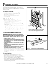
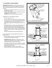
• Install a ceiling fi restop whenever the chimney penetrates
a fl oor/ceiling.
NOTICE: A maximum of two pairs of offsets and returns
may be used.
CAUTION! Risk of Fire and/or Asphyxiation! DO
NOT connect this fi replace to a chimney fl ue servicing
another appliance. DO NOT connect to any air distribu-
tion duct or system. These actions could cause over-
heating/fi re in the chimney fl ue, or release of exhaust
fumes into the living areas.
Heat & Glo • HST-42D • 27177 • Rev AB • 11/08
HEIGHT OF CHIMNEY COMPONENTS in. mm
Chimney Stabilizer
SL3 4-3/4 121
Ceiling Firestops
FS338 0 0
FS339 0 0
FS340 0 0
Offsets/Returns
SL315 13-3/8 340
SL330 15-1/2 394
Roof Flashing
RF370 0 0
RF371 0 0
Chimney Sections*
SL306 4-3/4 121
SL312 10-3/4 273
SL318 16-3/4 425
SL324 22-3/4 578
SL336 34-3/4 883
SL348 46-3/4 1187
* Dimensions refl ect effective height.