


Special offers from our partners!

Find Replacement BBQ Parts for 20,308 Models. Repair your BBQ today.

20
40 in.
[1016 mm]
36 in.
[914 mm]
12 in.
[305 mm]
9 3/4 in.
[248 mm]
12 in.
[305 mm]
12 in.
[305 mm]
Grid represents 1 in. (25 mm) squares
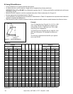
FLUSH
FRONT
4 in.
[102 mm]
BRICK
FRONT
50° angle
39° angle
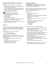
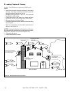
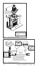
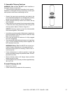
D. Frame the Fireplace
Figure 6.4 shows typical framing using combustible materials (2x4 lumber shown).
• Observe all required air space clearances to combustible materials as shown in Figure 6.1 & 6.2.
• Framing across the top of fi replace must be above top standoffs.
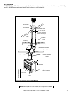
You must maintain
2 in. (51 mm) min. air space
clearance from the
chimney to the
enclosure.
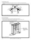
23 in.
(584 mm)
Note: Fireplace
Header cannot be
positioned until after
the fireplace assembly
is in place.
41 in.
(1041 mm)
Figure 6.4 Framing the Fireplace
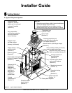
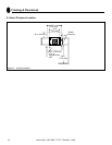
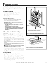
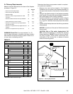
C. Sidewalls/Surrounds
• Adjacent combustible sidewalls must be located a minimum of 12 in. (305 mm) from the fi replace opening.
• Combustible and noncombustible mantel legs, surrounds and stub walls may be constructed within the gridded area,
Figure 6.3.
Figure 6.3 Mantel Leg or Wall Projections (Acceptable on both sides of opening)
Heat & Glo • HST-42D • 27177 • Rev AB • 11/08