


Special offers from our partners!

Find Replacement BBQ Parts for 20,308 Models. Repair your BBQ today.
www.fmiproducts.com
125636-01A 9
INSTALLATION
Continued
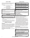
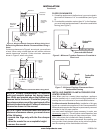
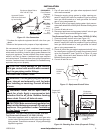
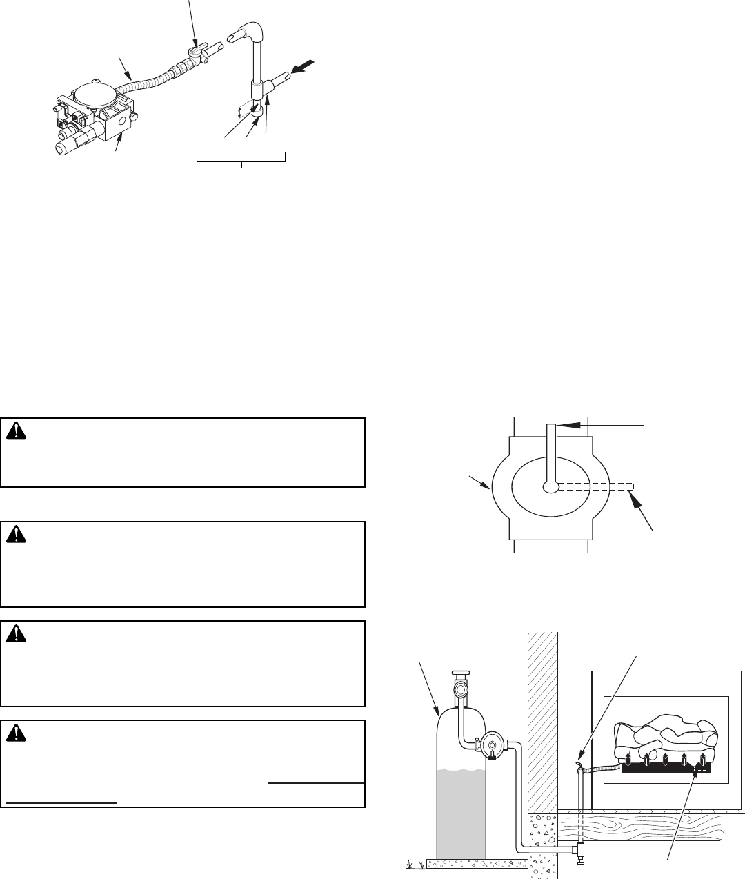
We recommend that you install a sediment trap in supply
line as shown in Figure 12. Locate sediment trap where it is
within reach for cleaning. Install in piping system between fuel
supply and appliance. Locate sediment trap where trapped
matter is not likely to freeze. A sediment trap traps moisture
and contaminants. This keeps them from going into appliance
controls. If sediment trap is not installed or is installed wrong,
appliance may not run properly.
CAUTION: Avoid damage to gas control.
Hold gas control with wrench when connect-
ing it to gas piping and/or ttings.
CHECKING GAS CONNECTIONS
WARNING: Test all gas piping and connec-
tions, internal and external to unit, for leaks
after installing or servicing. Correct all leaks
at once.
WARNING: Never use an open ame to
check for a leak. Apply a noncorrosive leak
detection uid to all joints. Bubbles forming
show a leak. Correct all leaks at once.
CAUTION: Make sure external regulator has
been installed between propane/LP supply and
appliance. See guidelines under Connecting
to Gas Supply, page 8.
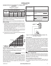
PRESSURE TESTING GAS SUPPLY PIPING SYSTEM
Test Pressures In Excess Of 1/2 PSIG (3.5 kPa)
1. Disconnect appliance with its appliance main gas valve
(control valve) and equipment shutoff valve from gas supply
piping system. Pressures in excess of 1/2 psig will damage
appliance regulator.
* Purchase the optional equipment shutoff valve from your
dealer.
**Minimum inlet pressure for purpose of input adjustment.
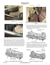
Figure 12 - Gas Connection
Pipe Cap Tee
Nipple Joint
Gas Control
3" Minimum
Sediment Trap
Equipment Shutoff Valve
With 1/8" NPT Tap*
Approved Flexible
Gas Hose (if allowed
by local codes)
PROPANE/LP
From External
Regulator
(11" W.C.**
to 14" W.C.
Pressure)
NATURAL
From Gas
Meter
(5" W.C.**
to 10.5"
W.C.
Pressure)
2. Cap off open end of gas pipe where equipment shutoff
valve was connected.
3. Pressurize supply piping system by either opening pro-
pane/LP supply tank valve for propane/LP gas or opening
main gas valve located on or near gas meter for natural
gas or using compressed air.
4. Check all joints of gas supply piping system. Apply noncor-
rosive leak detection uid to all joints. Bubbles forming show
a leak.
5. Correct all leaks at once.
6. Reconnect appliance and equipment shutoff valve to gas
supply. Check reconnected ttings for leaks.
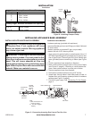
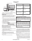
Test Pressures Equal To or Less Than 1/2 PSIG (3.5 kPa)
1. Close equipment shutoff valve (see Figure 13).
2. Pressurize supply piping system by either opening pro-
pane/LP supply tank valve for propane/LP gas or opening
main gas valve located on or near gas meter for natural
gas or using compressed air.
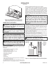
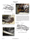
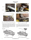
3. Check all joints from gas meter to equipment shutoff valve
for natural gas or propane/LP supply to equipment shutoff
valve for propane/LP (see Figure 14 or Figure 15, page
10). Apply noncorrosive leak detection uid to all joints.
Bubbles forming show a leak.
4. Correct all leaks at once.
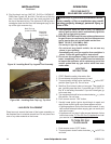
Figure 13 - Equipment Shutoff Valve
Open
Closed
Equipment
Shutoff
Valve
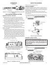
Figure 14- Checking Gas Joints (Propane/LP Only)
Control Valve
Location
Propane/LP
Supply Tank
Equipment
Shutoff Valve