


Special offers from our partners!

Find Replacement BBQ Parts for 20,308 Models. Repair your BBQ today.
www.fmiproducts.com
125636-01A
16
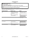
CLEANING AND MAINTENANCE
Continued
INSPECTING BURNERS
Continued
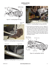
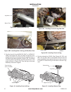
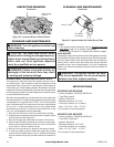
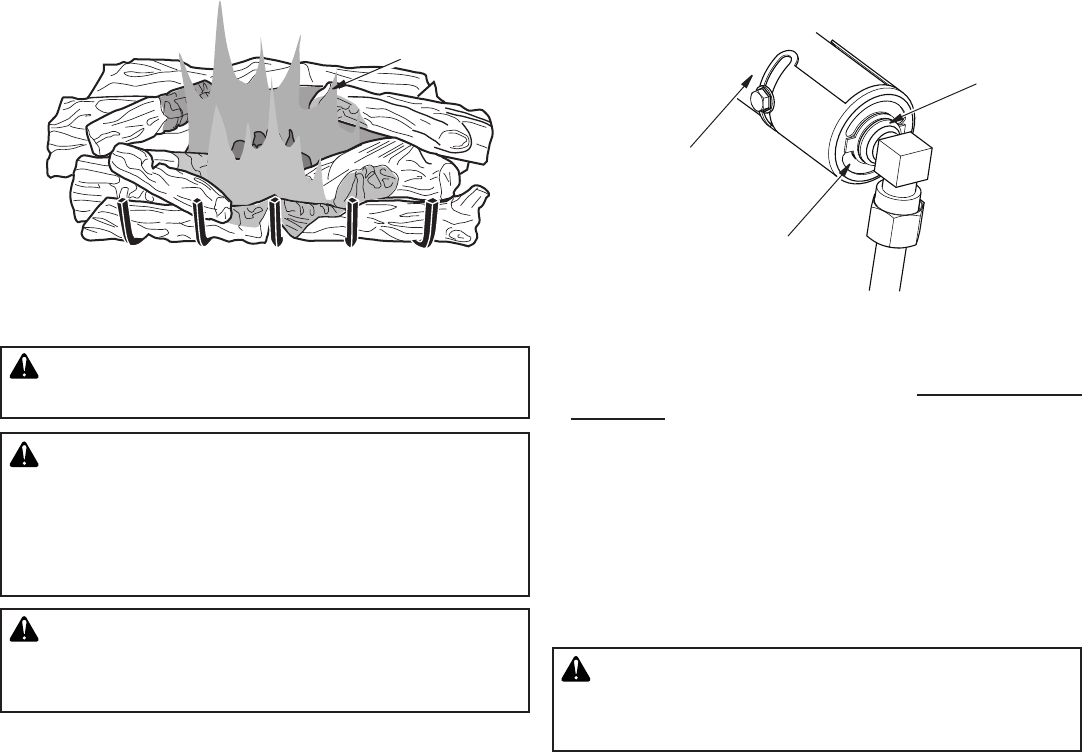
Figure 30 - Incorrect Burner Flame Pattern
Dark Orange
Flames
CLEANING AND MAINTENANCE
WARNING: Turn off appliance and let cool
before cleaning.
CAUTION: You must keep control areas,
burners and circulating air passageways of ap-
pliance clean. Inspect these areas of appliance
before each use. Have appliance inspected
yearly by a qualied service person.
WARNING: Failure to keep the primary air
opening(s) of the burner(s) clean may result
in sooting and property damage.
BURNER INjECTOR HOLDER AIR INLET HOLE
The primary air inlet holes allow the proper amount of air to
mix with the gas. This provides a clean burning ame. Keep
these holes clear of dust, dirt, lint and pet hair. Clean these air
inlet holes prior to each heating season. Blocked air holes will
create soot. We recommend that you clean the unit every three
months during operation and have appliance inspected yearly
by a qualied service person.
We also recommend that you keep the burner tube clean and
free of dust and dirt. To clean these parts we recommend using
compressed air no greater than 30 PSI. Your local computer
store, hardware store or home center may carry compressed
air in a can. If using compressed air in a can, please follow
the directions on the can. If you don’t follow directions on the
can, you could damage the pilot assembly.
1. Shut off unit. Allow unit to cool for at least thirty minutes.
2. Inspect burner, and primary air inlet holes on injector holder
for dust and dirt (see Figure 31).
3. Blow air through the ports/slots and holes in the burner.
4. Check injector holder located at end of burner tube again.
Remove any large particles of dust, dirt, lint or pet hair with
a soft cloth or vacuum cleaner nozzle.
5. Blow air into the primary air holes on the injector holder.
6. In case any large clumps of dust have now been pushed
into the burner repeat steps 3 and 4. Additional cleaning
may be needed for proper operation based on use/lack of
use.
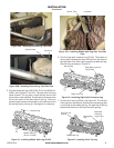
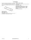
Figure 31 - Injector Holder On Outlet Burner Tube
Burner Tube
Injector
Holder
Primary Air
Inlet Holes
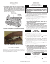
LOGS
• If you remove logs for cleaning, refer to Installing Logs and
Lava Rock, page 10, to properly replace logs.
• Replace log(s) if broken or chipped (dime-sized or larger).
MAIN BURNER
Periodically inspect all burner ame holes with appliance running.
All slotted burner ame holes should be open with ame present.
All round burner ame holes should be open with a small blue
ame present. Some burner ame holes may become blocked
by debris or rust, with no ame present. If so, turn off appliance
and let cool. Remove blockage, blocked burner ame holes will
create soot.
WARNING: The injector holders (air shut-
ters) are not adjustable. Do not move injector
holders from their original positions.
SPECIFICATIONS
MF42ONE AND MF48ONE
• Rating (Variable): 29,000/40,000 Btu/Hr
• Type Gas: Natural
• Ignition: Electronic
• Manifold Pressure: 3.4" W.C.
• Inlet Gas Pressure (in. of water):
Max - 10.5" W.C., Min* - 5" W.C.
*For purpose of input adjustment
MF42OPE AND MF48OPE
• Rating (Variable): 29,000/40,000 Btu/Hr
• Type Gas: Propane/LP
• Ignition: Electronic
• Manifold Pressure: 10.0" W.C.
• Inlet Gas Pressure (in. of water):
Max - 14" W.C., Min* - 11" W.C.
*For purpose of input adjustment