


Special offers from our partners!

Find Replacement BBQ Parts for 20,308 Models. Repair your BBQ today.
www.fmiproducts.com
125636-01A 7
INSTALLATION
Continued
INSTALLING APPLIANCE BASE ASSEMBLy
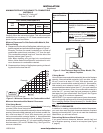
Area of Various Standard Round Flues
Diameter Area
5" 20 sq. inches
6" 29 sq. inches
7" 39 sq. inches
8" 51 sq. inches
Chimney Height Minimum Permanent Flue Opening
6' to 15' 39 sq. inches
15' to 30' 29 sq. inches
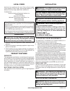
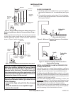
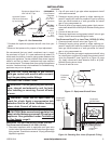
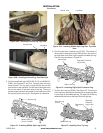
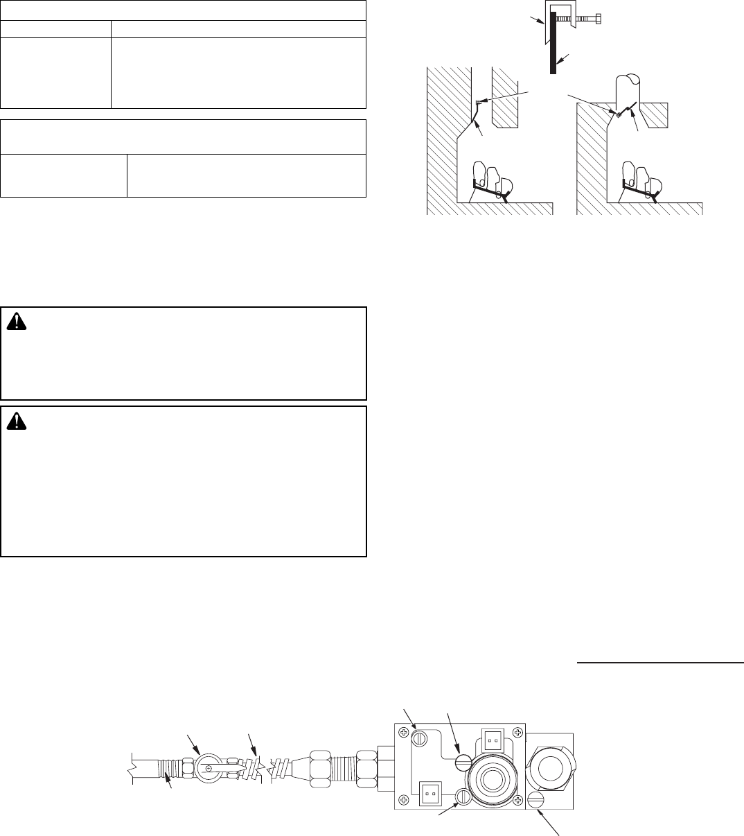
Figure 8 - Attaching Damper Clamp
Damper
Damper
Clamp
Damper
Damper
Clamp
Damper
Manufactured Fireplace
Masonry Fireplace
INSTALLING APPLIANCE BASE ASSEMBLY
WARNING: You must secure this appliance
to replace oor. If not, appliance will move
when you adjust controls. Moving appliance
may cause a gas leak.
WARNING: If installing in a sunken replace,
special care is needed. You must raise the re-
place oor to allow access to appliance control
panel. This will insure adequate air ow and
guard against sooting and controls being dam-
aged. Raise replace oor with noncombustible
material. Make sure material is secure.
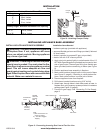
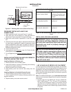
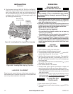
Figure 9 - Connecting Incoming Gas Line to Flex Gas Line
Note:
1) Wire connections not
shown for clarity
2) * 1/8" NPT Plugged
Tapping
MAIN
IN
OUT
PILOTADJ
PILOT
Pilot Adjustment
Inlet Pressure Tap
Outlet Pressure Tap
Gas Shutoff
Valve
Flexible
Gas Line
Do NOT
Kink
1/2" NPT
Incoming
Gas Line
Set Screw
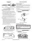
Installation Items Needed
• hardware package (provided with appliance)
• approved exible gas hose and ttings provided (if allowed
by local codes)
• sealant (resistant to propane/LP gas, not provided)
• electric drill with 3/16” masonry drill bit
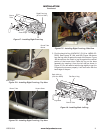
1. Apply pipe joint sealant lightly to male threads of the 1/2
NPT side of gas tting elbow (provided) and connect to inlet
side of gas control. Remove gas tting from exible gas
hose (provided) before connecting to elbow (see Figure
9).
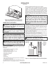
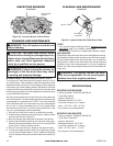
2. Position appliance base assembly in replace.
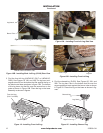
3. Mark screw locations through holes in front panel of base
(see Figure 10, page 8). If installing in a brick-bottom re-
place, mark screw locations in mortar joint of bricks.
4. Remove appliance base from replace.
5. Drill holes at marked locations using 3/16" drill bit.
6. Attach base, through holes in back side panels of base, to
replace oor using masonry screws provided in hardware
package (see Figure 10, page 8).
7. Connect to gas supply. See Connecting To Gas Supply,
page 8.