


Special offers from our partners!

Find Replacement BBQ Parts for 20,308 Models. Repair your BBQ today.

www.fmiproducts.com
125636-01A
10
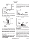
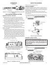
INSTALLING BATTERIES IN HAND HELD REMOTE
CONTROL AND BATTERY PACK
Installing Batteries in Battery pack
1. Remove access cover on battery pack.
2. Install 4 AA batteries, included, into battery pack following
positive and negative directions.
3. Replace access cover on battery pack.
4. Place battery pack next control valve away from the
burner.
Installing Batteries in Handheld Remote Control
1. Remove battery cover on back of remote control.
2. Install supplied A23/12V battery following positive and
negative directions.
3. Replace battery cover onto remote control.
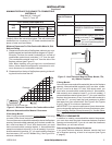
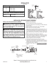
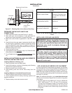
Gas Meter
Figure 15 - Checking Gas Joints (Natural Gas Only)
Control Valve
Location
Equipment Shutoff Valve
INSTALLATION
Continued
PRESSURE TESTING APPLIANCE GAS
CONNECTIONS
1.
Open equipment shutoff valve (see Figure 13, page 9).
2. Open main gas valve located on or near gas meter for
natural gas or open propane/LP supply tank valve.
3. Make sure control knob of appliance is in the OFF posi-
tion.
4. Check all joints from gas meter to equipment shutoff valve
for natural gas or propane/LP supply to equipment shutoff
valve for propane/LP (see Figure 14, page 9 or Figure 15,
page 10). Apply noncorrosive leak detection uid to all joints.
Bubbles forming show a leak.
5. Correct all leaks at once.
6. Light appliance (see Operation, page 14). Check all other
internal joints for leaks.
7.
Turn off appliance (see To Turn Off Gas to Appliance, page
14).
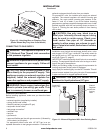
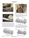
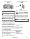
Figure 16 - MF Series Burner System- Log Compatibility
Chart
INSTALLING LOGS AND LAVA ROCK
WARNING: Failure to position the parts in
accordance with these diagrams or failure to
use only parts specically approved with this
appliance may result in property damage or
personal injury.
CAUTION: After installation and periodically
thereafter, check to ensure that no ame comes
in contact with any log. With appliance set to
Hi, check to see if ames contact any log. If
so, reposition logs according to log installation
instructions in this manual. Flames contacting
logs will create soot.
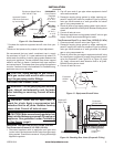
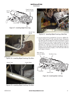
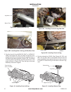
LMF (42 AND 48)-SC SERIES LOG PLACEMENT
It is very important to install these logs exactly as instructed.
Do not modify logs. Only use logs supplied with appliance or as
identied for use with the appliance as shown in Figure 18.
Note: Each log includes an identifying number cast in the log.
Look at each log when placing them on the burner system to
be certain it is correct.
Note: For additional information, go to www.fmiproducts.com
and click on the technical Support tab for access to log place-
ment videos.
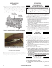
Find the right front log (LMF42-SC: D-019 or LMF48-SC: 1.
D027). See Figures 17, 17A, 17B, and 17C for reference.
The log has a rectangular shape on the bottom that ts
against the lip on the black metal base, the square grate,
and the round tube burner. Slide the log in place as shown
in Figures.
Burner System Model
MF42ONE,MF42OPE,
MF48ONE, MF48OPE,
Refractory Concrete Logs
For Use With This Burner
System
LMF42-SC
LMF48-SC
MF SERIES BURNER SYSTEM-LOG COMPATIBILITY
CHART