


Special offers from our partners!

Find Replacement BBQ Parts for 20,308 Models. Repair your BBQ today.

www.fmiproducts.com
125636-01A 15
OPERATION
Continued
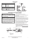
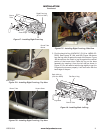
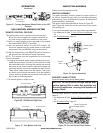
Figure 25 - Turning Equipment Shutoff Valve to the OFF
Position
MAIN
IN
OUT
PILOTADJ
PILOT
Equipment
Shutoff Valve
Incoming
Gas Line
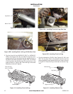
GAS CONTROL MODULE SySTEM
REMOTE CONTROL FEATURE
The module has a built in remote control receiver that
allows the user to program the remote transmitter at
any time during or after the installation of the burner.
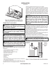
1. There is a switch located on the right side of the module
that reads REMOTE/OFF (Figure 26).
2. When the remote/off switch is in the OFF position, the
burner will operate from the rocker switch or wall switch
connected to the two BROWN wires on the module.
3. When the remote/off is in the REMOTE position the burner
will operate from the Remote Control transmitter.
NOTE: The module must be programmed to the Remote
Control transmitter.
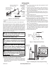
To program the module (make sure the system has power), •
locate the learn button (Figure 27) on the module. Locate
the metal shield that is covering the module and remove
the screw on top. Use a small thin object like a paper clip
(not sharp points) to press and release the learn button.
There will be a beep sound from the module. Then press
any button on the remote transmitter. Once the module's
internal receiver accepts the transmitter code, there will
be a series of conrming beeps.
The remote system is ready for use.•
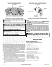
Remote/Off Switch
ADJ.
“S” Pilot Connection
“I” Pilot Connection
AF-4000 MOD Module Rt Side
Figure 26 - Gas Module Right Side
AF-4000 MOD Module Lt Side
AUX Connection
Learn Button
Figure 27 - Gas Module Left Side
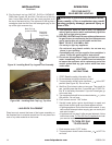
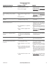
INSPECTING BURNERS
Check burner ame patterns often.
IGNITOR ASSEMBLY
The ignitor assembly is factory preset for proper ignition of
the burner. Alterations may have occurred during shipping
and handling. Call a qualied service person to readjust the
ignitor assembly if necessary.
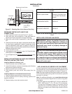
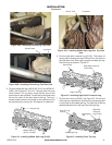
The ignitor should be positioned as shown in Figure 28.
Note: Figure 28, shows the correct positioning of the ignitor
and sensing rod.
If your ignitor assembly does not meet these requirements:
• turn appliance off (see To Turn Off Gas to Appliance, page
14).
• see Troubleshooting, page 18
Figure 28 - Ignitor Assembly
Ignitor
Ignitor
Sensing Rod
Burner
Tube
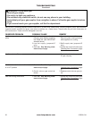
Figure 29 - Correct Burner Flame Pattern
Yellow Flames with
Orange Streaks
BURNER FLAME PATTERN
Figure 29 shows correct burner ame pattern.
NOTICE: Do not mistake orange ames with
yellow tipping. Dirt or other ne particles are
burned by appliance, causing brief patches of
orange ame.
If burner ame pattern is incorrect, as shown in Figure 30,
page 16.
• turn appliance off (see To Turn Off Gas to Appliance, page
14)
• see Troubleshooting, page 18