


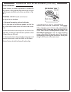
Special offers from our partners!

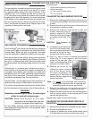
Find Replacement BBQ Parts for 20,308 Models. Repair your BBQ today.
32
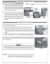
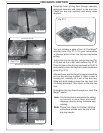
4. Remove the back panel by pulling the bottom toward
the front of the grill and rotating it upward and
outward until the two top tabs attached to back wall
of the oven can be removed from the slots in the top
of the plate.
5. Remove the backburner
assembly retaining screw on the
lower left of the backburner using
a Phillips-head screwdriver and
set it aside.
6. Pull the backburner assembly
to the left, clear of the orifi ce,
and then rotate the top forward
and downward and lay it face
down across the cooking grids
or main burners.
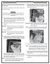
CAUTION: Be careful not
to damage the
wires connected
to the backburner
assembly.
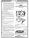
7. Use a
3
/
8
" hex nut driver
to remove the exposed
orifi ce and replace it with
the correct orifi ce for the
gas being converted to
(See Table 1 for size).
8. Replace the backburner assembly and reinsert the
retaining screw. Center the backburner assembly so
that the backburner plate will fi t over it. Tighten the
retaining screw using a Phillips-head screwdriver.
9. Replace the back panel by fi rst inserting the tabs
above into the slots in the top of the plate and then
rotating the bottom downward and inward.
10. Replace all the backburner plate screws using a
Phillips-head screwdriver.
CHANGING AN INFRARED BURNER ORIFICE
(IF EQUIPPED)
1. Remove the cooking grid from above the burner on
which you are working by lifting it fi rst from the front
and set it aside.
2. Unscrew both lighting tube hex head screws with a
3
/
8
" hex nut driver.
3. Remove the infrared burner by lifting the back of the
burner up so that both tabs are freed from their slots,
then lift the burner toward the back of the fi re box
and upward. Set the burner aside.
4. Use a
3
/
8
" hex nut driver to remove the exposed orifi ce
and replace it with the proper orifi ce for the new gas
(see Table 1 for sizing).
5. Replace the infrared burner by fi rst sliding it over the
orifi ce, then lowering the two tabs under the back of
the burner into the slots in the back burner rest.
6. Reattach the lighting tube and replace the grid so
that the cut-out section is in front.
CONVERTING THE GAS TYPE
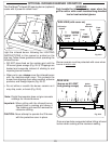
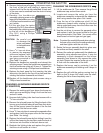
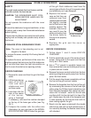
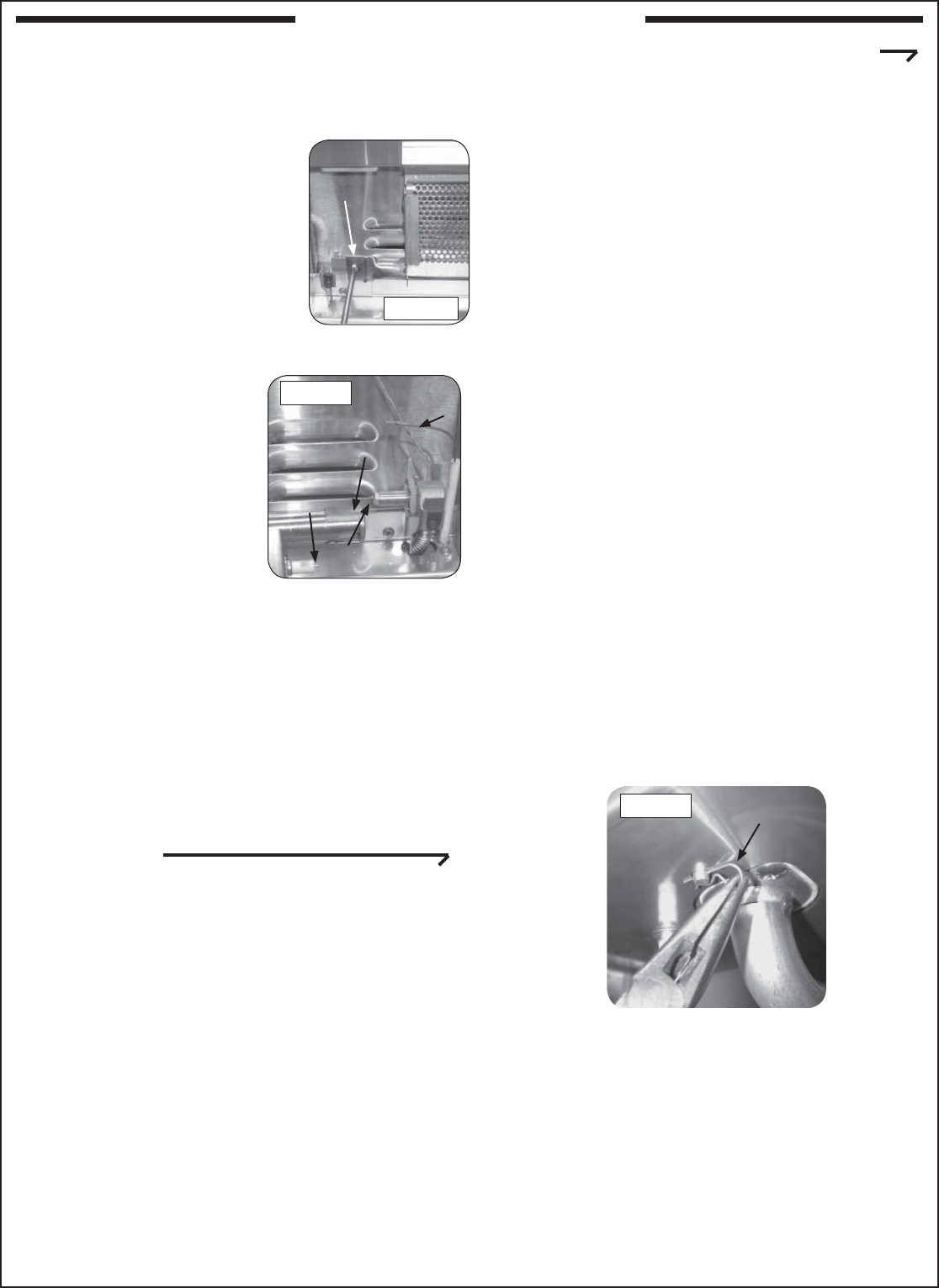
6. Pull the wire from the ignitor
electrode (Fig. 32-2), then remove
the backburner retaining screw
on the left of the backburner
(Fig. 32-1) using a Phillips
screwdriver.
Fig. 32-2
Backburner
orifi ce
Backburner
air shutter
Backburner
electrode
Electrode wire
(disconnected)
Fig. 32-1
Retaining
screw
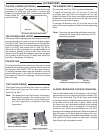
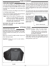
CHANGING THE SIDEBURNER ORIFICE
1. Lift the sideburner lid. Then remove the grill and
sideburner cap and set them aside.
2. Locate and remove the cotter pin from the
sideburner assembly underneath the sideburner
shelf using needle-nose pliers. Set it aside.
3. From the top of the sideburner shelf, lift the
sideburner upward while rotating the attached
tubing underneath away from the orifi ce near the
cart wall. Set it aside.
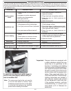
4. Use the nut driver to remove the exposed orifi ce
and replace it with the correct orifi ce for the gas
being converted to. (See Table 1 for correct orifi ce
sizes based on burner type and gas type.)
Note: To protect the manifold threads when placing
the new orifi ce, start the threading manually,
and then tighten with the nut driver.
5. Rotate the burner assembly back into place over
the orifi ce and fi rmly seated in the shelf.
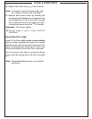
6. Reinsert the cotter pin underneath the sideburner
assembly using needle-nose pliers. It may be
necessary to push downward on the burner
assembly from above to fully expose the cotter
pin hole. Rotate the inserted cotter pin so that it
is fl ush with the underside of the shelf.
7. Replace the burner cap by centering it on the
sideburner assembly and making sure it drops in
place.
8. Replace the grill with the grating running front to
back so that it drops fully down onto the shelf,
allowing the lid to close completely over it.
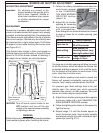
Fig. 32-3
Cotter
pin