


Special offers from our partners!

Find Replacement BBQ Parts for 20,308 Models. Repair your BBQ today.

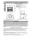
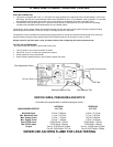
5. ELECTRICAL REQUIREMENTS
The ACCENT 25 will operate without electrical power. This model has a Millivolt gas control which uses the pilot flame to
generate enough electricity to operate the main burners. The appliance when equipped with blower must be electrically
connected and grounded in accordance with local codes or in the absence of local codes, with the current CSA C22.1
CANADIAN ELECTRICAL CODE Part 1, SAFETY STANDARDS FOR ELECTRICAL INSTALLATIONS, OR THE NATIONAL
ELECTRICAL CODE ANSI / NFPA 70 in the U.S.
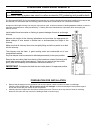
WARNING: Electrical
grounding instructions. This
appliance is equipped with a
three-prong (grounding) plug for
your protection against shock
hazard, and should be plugged
directly into a properly
grounded three-prong outlet.
DO NOT cut or remove the
grounding prong from this plug.
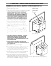
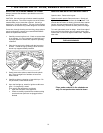
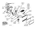
REMOVING / INSTALLING THE BLOWER
1. Turn the unit off, open the door and remove the log set. Remove
brick panel(s) (see Removing and Installing Brick Panels). Remove
the burner tray assembly by removing the two (2) screws on either
side of the tray. Pull tray up at the back and lift out.
2. Disconnect the gas line to the nipple. Remove the three (3) screws
holding the burner control tray to the back firewall. Lift tray up on left
side and pull out.
3. Pull blower towards you. Disconnect wires from the blower and
remove.
4. To re-install perform the preceding steps in reverse.
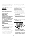
CAUTION: Label all wires prior
to disconnection when servicing
controls. Wiring errors can
cause improper and dangerous
operation. Verify proper
operation after servicing
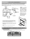
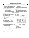
INSTALLING REMOTE THERMOSTAT OR WALL SWITCH
RECOMMENDED WIRE SIZE for thermostat installation: 18 gauge, 2 wire solid core, Low Voltage wire. (Bell wire)
1. Install the 18 Gauge wire supplied to the two terminals on the thermostat or remote wall switch.
2. Connect the other end of the wire to the gas valve using the two outside terminals on the front of the gas valve.
Use the terminals marked (TP/TH and TH).
RECOMMENDED MAXIMUM LEAD LENGTH (TWO WIRE)
WHEN USING WALL THERMOSTAT
WIRE SIZE
MAXIMUM LENGTH
14 GAUGE 100 FEET
16 GAUGE 64 FEET
18 GAUGE 40 FEET
20 GAUGE 18 FEET
8