


Special offers from our partners!

Find Replacement BBQ Parts for 20,308 Models. Repair your BBQ today.
www.desatech.com
110112-01C 11
INSTALLATION
Continued
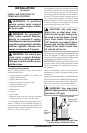
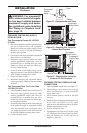
For Recessed Installation
If fireplace is to be recessed into a wall (see
Built-In Fireplace Installation, page 17), we
recommend mounting wall switch assembly to
left side of fireplace. The wall switch assembly
should be mounted approximately 12" from left
edge of fireplace, and less than 60" from the floor.
IMPORTANT: Do not locate wall switch assembly
directly in front of wall stud - there must be room
behind wall board for wires from switch. If you
choose to locate wall switch assembly to right side
of fireplace, the length of the cord restricts you to
less than 6" from right edge of fireplace and less
than 48" from floor.
For Mantel Installation
If fireplace is to be installed into a mantel, (see
Conventional Fireplace Installation, page 16) the
wall switch assembly may be mounted on either
side of the mantel, facing to the side. Do not locate
wall switch assembly anywhere on the front face
of the mantel.
CAUTION: Be careful of gas
lines and wiring when moving
floor.
1. Determine the new location for the wall switch
assembly. The wires attached to switch are six
feet long.
2. Remove 2 screws securing plastic wall switch
assembly to bracket in fireplace lower cavity.
Save screws.
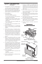
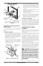
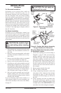
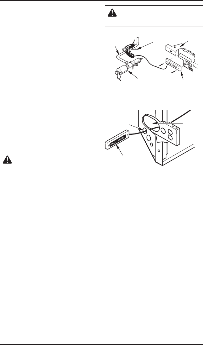
3. Remove wire tie holding coiled wire attached
to wall switch assembly (see Figure 8).
4. Remove wall switch assembly from bracket.
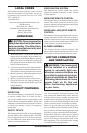
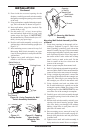
5. Carefully pass wall switch assembly and cord
through large elongated hole in rear of either
left or right floor support bracket, depending on
desired location of switch. Pass wall switch as
-
sembly and cord through 1.5" diameter hole in
side of fireplace outer casing (see Figure 9).
6. Pull wall switch assembly and cord from
fireplace making sure wall switch assembly
will reach desired mounting location without
straining cord assembly.
If you are mounting wall switch assembly to a
wall, continue reading. If you are mounting your
wall switch assembly to the side of the mantel,
see page 12.
CAUTION: Do not apply ex-
cessive pull on cord.
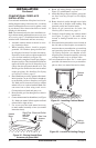
Figure 8 - Relocating Wall Switch
Assembly
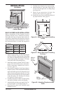
Figure 9 - Routing Wall Switch Assembly
Through Fireplace for Relocation
Wall Switch
Assembly
Wire Tie
Burner
Outlet
Tube
Gas Control
Valve
Firebox
Bottom
Wall Switch
Assembly
Hole in
Outer
Casing
Hole in
Floor
Support
Bracket
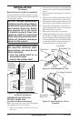
Mounting Wall Switch Assembly to Wall
for Recessed Fireplace
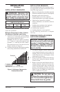
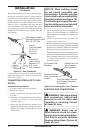
7. Create three openings on wall according to
Template 1, page 35. This is best done by
making a pattern to work with on your wall.
Carefully cut page 35/36 from manual and
tape paper template vertically onto wall at
preferred location. Pierce the paper at the cen-
ters of the 2 holes with a nail or sharp pencil,
leaving a mark on the wall. Do the same at
centers of the four circles near the corners of
the rectangle.
8. Remove paper template from wall.
9. Drill 3/8" holes at each mark.
10. Using a straight edge and pencil, connect the
outer edges of the 4 holes for the rectangle
(see Figure 10, page 12). This will give you
cutting lines for the rectangle you will cut in
the wall.
11. Using a keyhole saw, hack saw blade, drill,
file, or other suitable tool, carefully cut out the
rectangular opening. Note: The corners of the
rectangle may be round. IMPORTANT: Do not
exceed the size of the rectangle on template.