


Special offers from our partners!

Find Replacement BBQ Parts for 20,308 Models. Repair your BBQ today.
111285-01B
For more information, visit www.desatech.com
For more information, visit www.desatech.com
13
13
INSTALLATION
Continued
INSTALLATION
Checking Gas Connections (Cont.)
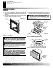
Fireplace Insert Installation Into Masonry Fireplace
Assembling And Attaching Trim
Pressure Testing Fireplace Insert Gas
Connections
1. Open equipment shutoff valve (see Figure 17, page 12).
2. Open main gas valve located on or near gas meter for natural
gas or open propane/LP supply tank valve.
3. Make sure control knob of fireplace insert is in the OFF position.
4. Check all joints from gas meter to equipment shutoff valve for
natural gas (see Figure 18, page 12), or propane/LP supply to
equipment shutoff valve for propane/LP (see Figure 19, page 12).
Apply a noncorrosive leak detection fluid to all joints. Bubbles
forming show a leak.
5. Correct all leaks at once.
6. Light fireplace insert (see Operating Fireplace Insert, pages
16 through 18). Check all other internal joints for leaks.
7. Turn off fireplace insert (see To Turn Off Gas to Appliance,
page 17).
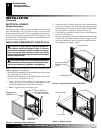
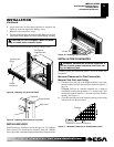
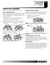
1. Use dimensions shown in Figure 20 for the masonry fire-
place opening.
2. Install and properly ground GA3555, three-prong 120 volt elec-
trical outlet, in fireplace insert. Follow instructions included
in kit (see Accessories, page 30).
35"
17
1
/
4
"
26
1
/
4
"
Figure 20 - Rough Opening for Installing in Masonry Fireplace
FIREPLACE INSERT INSTALLATION INTO
MASONRY FIREPLACE
Installation of this fireplace insert involves installing fireplace insert
into an existing masonry fireplace. If using a mantel above the fireplace,
you must follow the clearances shown in Figure 12, page 10. Follow the
instructions below to install the fireplace insert in this manner.
Minimum
Insert Fireplace Opening
Height 25
9
/16" 26
1
/4"
Front Width 34
5
/16" 35"
Depth 16
11
/16" 17
1
/4"
3. Install gas piping to fireplace location. This installation includes
an approved flexible gas line (if allowed by local codes) after
the equipment shutoff valve. The flexible gas line must be the
last item installed on the gas piping. See Installing Gas Piping
to Fireplace Location, pages 10 and 11.
4. Carefully set fireplace insert in front of masonry fireplace with
back of insert inside wall opening.
5. Attach flexible gas line to gas supply. See Connecting Fire-
place Insert to Gas Supply, pages 11 and 12.
6. Plug electrical cord into electrical outlet installed in step 2.
7. Carefully place fireplace insert into masonry fireplace.
8. Check all gas connections for leaks. See Checking Gas Con-
nections, pages 12 and 13.
9. Install trim after final finishing and/or painting of wall (see
Figure 22, page 14).
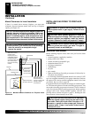
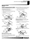
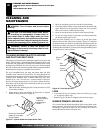
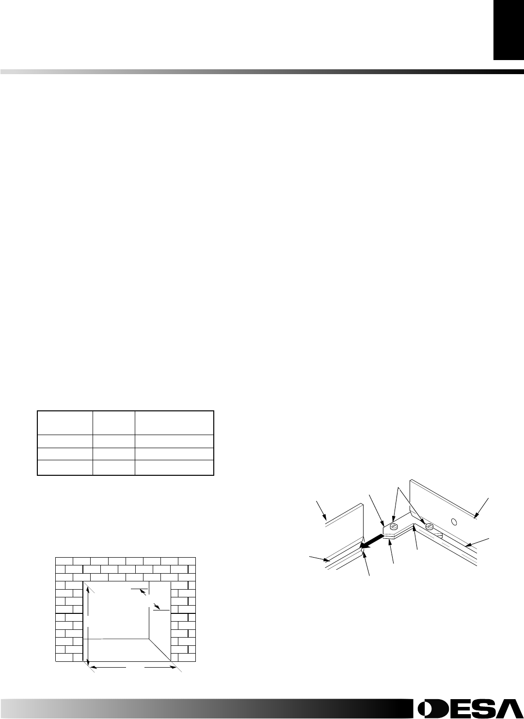
Slot
Side
Surround
Trim
Top Surround
Trim
Set
Screws
Adjusting
Plate
Slot
Mitered Edge
Figure 21 - Assembling Surround Trim
Shim
Mitered
Edge
ASSEMBLING AND ATTACHING TRIM
1. Remove three pieces of surround trim from packaging.
2. Locate four #6 screws, two adjusting plates with set screws,
and two shims in the hardware packet.
3. Align shim under adjusting plate as shown in Figure 21.
4. Slide one end of adjusting plate/shim in slot of top surround
trim (see Figure 21).
5. Slide other end of adjusting plate/shim in slot on mitered edge
of side surround trim (see Figure 21).
6. While firmly holding edges of trim together, tighten both set
screws on the adjusting plate with slotted screwdriver.
7. Repeat steps 3 through 6 for other side.