


Special offers from our partners!

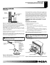
Find Replacement BBQ Parts for 20,308 Models. Repair your BBQ today.
111285-01B
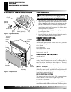
For more information, visit www.desatech.com
For more information, visit www.desatech.com
11
11
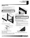
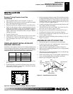
CSA Design-Certified
Equipment Shutoff Valve
With 1/8" NPT Tap*
Supplied Flexible
Gas Line
3" Minimum
Propane/LP
From External
Regulator (11"
W.C. to 14" W.C.
Pressure)
Natural
From Gas Meter
(5" W.C. to
10.5" W.C.
Pressure)
Cap Pipe Tee
Nipple Joint
Sediment Trap
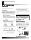
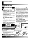
Figure 14 - Gas Connection
* Purchase the optional CSA design-certified equipment shutoff
valve from your dealer. See Accessories, page 30.
INSTALLATION
Continued
WARNING: Use pipe joint sealant that is resistant
to liquid petroleum (LP) gas.
Installation must include an equipment shutoff valve, and plugged 1/8"
NPT tap. Locate NPT tap within reach for test gauge hook up. NPT tap
must be upstream from fireplace insert (see Figure 14).
IMPORTANT:
Install equipment shutoff valve in an accessible
location. The equipment shutoff valve is for turning on or shutting
off the gas to the appliance.
Check your building codes for any special requirements for locating
equipment shutoff valve to fireplaces.
Apply pipe joint sealant lightly to male NPT threads. This will
prevent excess sealant from going into pipe. Excess sealant in pipe
could result in clogged fireplace valves.
INSTALLATION
Installing Gas Piping To Fireplace Location (Cont.)
Connecting Fireplace Insert To Gas Supply
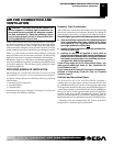
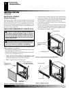
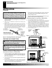
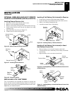
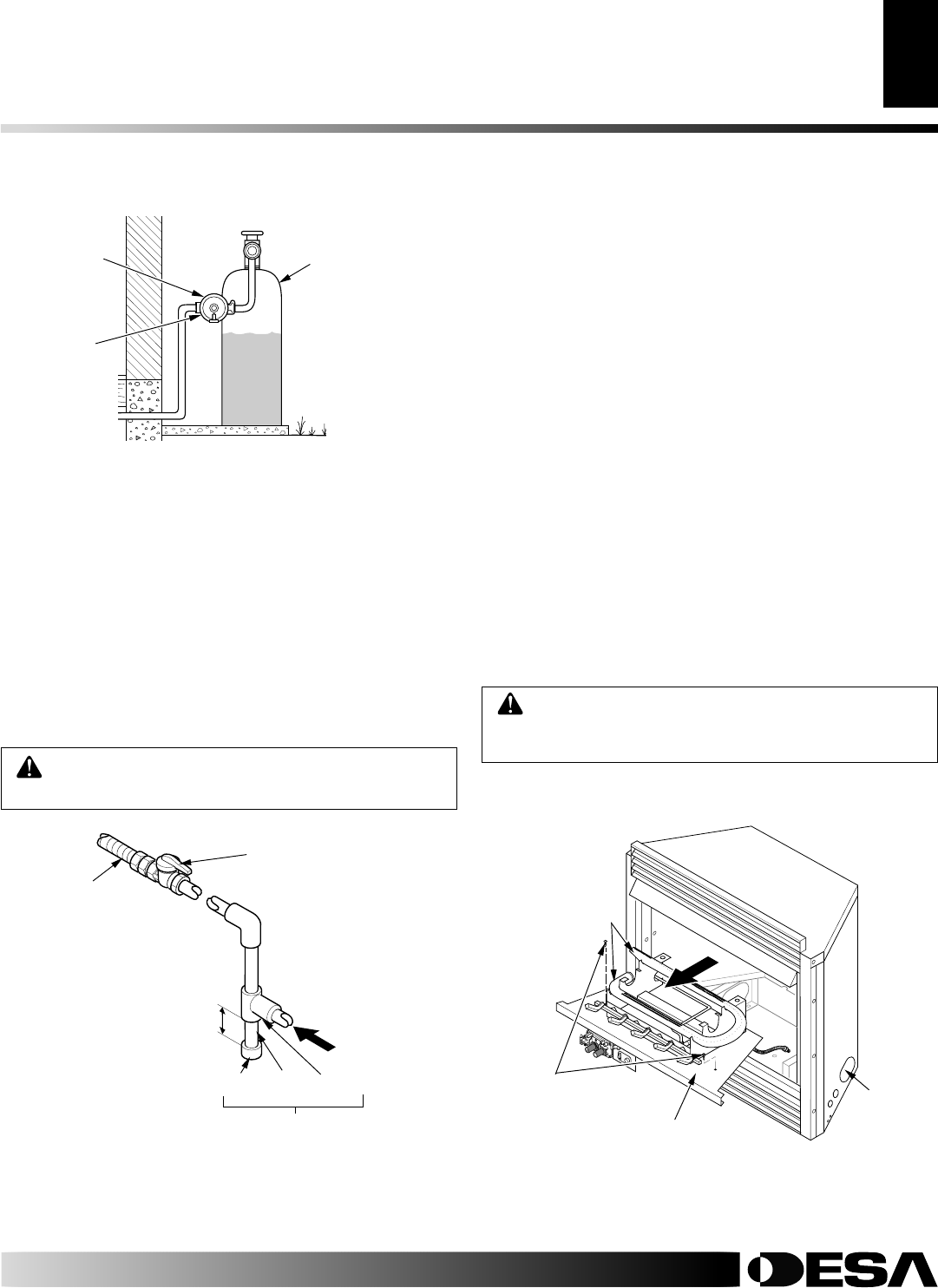
Figure 13 - External Regulator with Vent Pointing Down
Propane/LP
Supply
Tank
External
Regulator
Vent Pointing
Down
We recommend that you install a sediment trap in supply line as
shown in Figure 14. Locate sediment trap where it is within reach for
cleaning. Install in piping system between fuel supply and heater.
Locate sediment trap where trapped matter is not likely to freeze. A
sediment trap traps moisture and contaminants. This keeps them
from going into fireplace insert gas controls. If sediment trap is not
installed or is installed wrong, fireplace may not run properly.
CONNECTING FIREPLACE INSERT TO GAS
SUPPLY
Installation Items Needed
• 5/16" hex socket wrench or nut-driver
• Phillips screwdriver
• sealant (resistant to propane/LP gas, not provided)
1. Remove fireplace insert screen. Lift fireplace insert screen up
and pull out to remove.
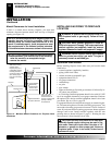
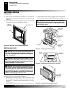
2. Remove screws that attach log base assembly to fireplace in-
sert (see Figure 15). Carefully lift up log base assembly and
remove from fireplace insert (see Figure 15).
Note:
If adding the G8010 series brick liner accessory, install it
now. Follow instructions in G8010 accessory kit.
CAUTION: Do not pick up log base assembly by
burners. This could damage burners. Only handle
base by grates.
3. Route gas supply line through access opening of fireplace in-
sert (see Figure 15).
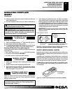
Figure 15 - Removing Log Base Assembly From Fireplace Insert
O
F
F
P
I
L
O
T
O
N
H
I
L
O
Burners
Two Screws
Log Base Assembly
Gas Line
Access