


Special offers from our partners!

Find Replacement BBQ Parts for 20,308 Models. Repair your BBQ today.
105706-01B
For more information, visit www.desatech.com
For more information, visit www.desatech.com
19
19
GAS SUPPLY TESTING
Note:
This section is intended as a guide for qualified service
technicians installing gas to the appliance.
CAUTION: Do not connect appliance before pres-
sure testing gas piping. Damage to the gas valve may
result and an unsafe condition may be caused.
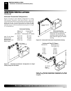
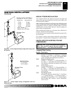
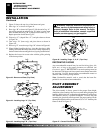
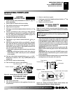
The millivolt system with a manual HI/LO applies only to the
VDVF36STN/STP and VDVF36PN/PP models. The gas control
valve is secured underneath the firebox with two brackets fastened
to the firebox bottom. Two pressure taps are provided on the gas
control valve for a pressure gauge connection (see Figure 40).
O
F
F
P
I
L
O
T
O
N
L
O
H
I
P
I
L
O
T
EA
16AI
7
TPTH TP TH
Figure 40 - Millivolt Control Valve
Pilot Adjustment Cap
ON/OFF
Knob
Outlet
Pressure
Inlet Pressure
INSTALLATION
Continued
WARNING: Improper installation, adjustment, al-
teration, service, or maintenance can cause injury or
property damage. Refer to this manual. For assis-
tance or additional information, consult a qualified
installer, service agency, or gas supplier.
GAS RATING
TYPE OF GAS NATURAL PROPANE/LP
Max. Input Rating: 30,000 Btu/hr 28,000 Btu/hr
Orifice Size (0-4,500 Ft.): 7/64" #52
Min. Input Rating: 21,000 Btu/hr 20,000 Btu/hr
(When the Valve is in
the LOW Position)
* Max. Output Rating: 21,000 Btu/hr 20,000 Btu/hr
Manifold Pressure: 3.5 in. WC 10.0 in. WC
**Min. Supply Pressure: 4.5 in. WC 11.0 in. WC
**Max. Supply Pressure: 10.5 in. WC 13.0 in. WC
* 70% Efficiency (flue loss calculation).
* For the purpose of input adjustment.
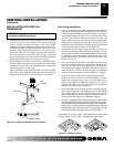
INSTALLATION
Gas Line Hook-Up (Cont.)
Gas Supply Testing
Installing Log Set
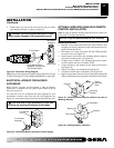
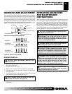
Pilot Gas Line -
Do Not Kink
To Pilot
Burner
To Main Burner
Flame Adjustment Knob
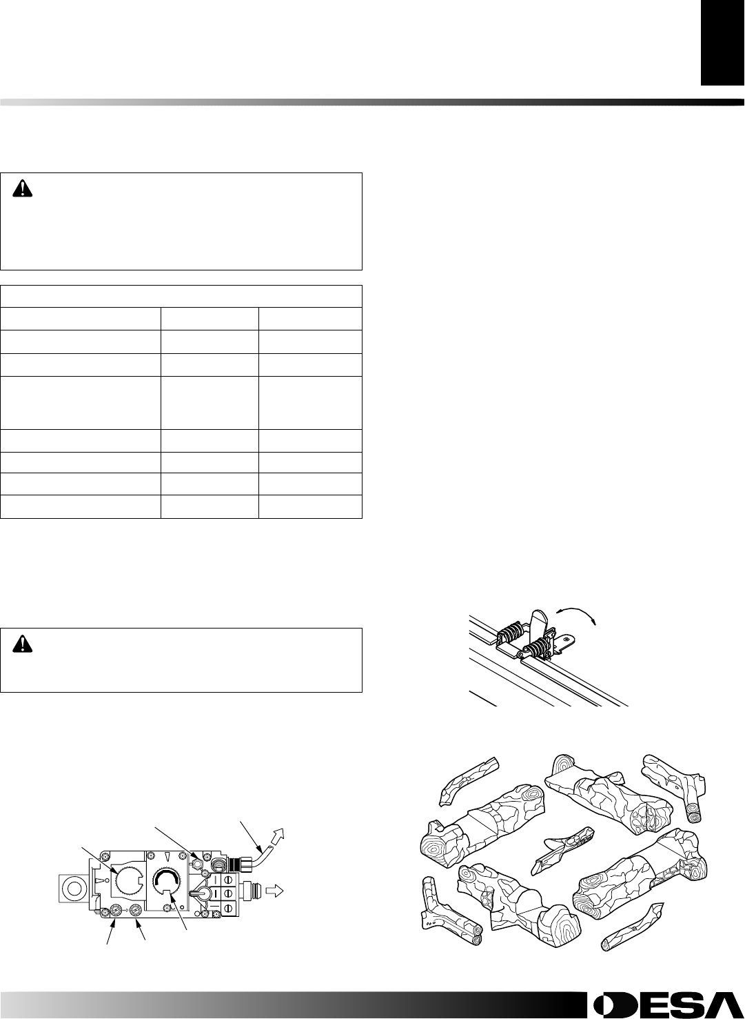
INSTALLING LOG SET
Before proceeding, make sure the gas control valve is in the “OFF”
position. Logs have been packaged separately to prevent damage to
glass or refractory.
1. Remove top and bottom louvers by simultaneously pulling both
top end spring latches towards the center of the appliance until
they are disengaged from locating holes. Repeat for bottom end
spring latches and pull outward. Reverse procedure to install
louvers back.
2. Remove the screen rod by sliding spring clip on one end to-
ward the center. Slide rod into screen rod hole until other end
of rod is free. Remove rod.
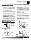
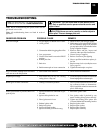
3. To open the glass door, open the pairs of latches located on the
top and bottom of the firebox (see Figure 41).
Note:
Use cau-
tion when opening these latches.
4. Carefully open the door. The glass door is mounted to the fire-
box with 5 screws.
5. To remove the logs from the shrink wrap, carefully cut the
plastic around the perimeter of the log. Do not try to remove
the logs from the package without first cutting the plastic.
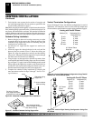
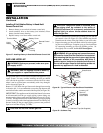
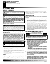
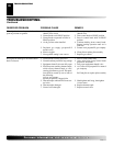
6. Figure 42 shows the log set. Logs “A” have the knot at the end
of the log. Logs “B” have the knot at the middle of the log.
Twigs “C” have the shape of a “Y”. Twigs “D” have the shape
of bent twigs. Twig “E” is a straight twig which is placed across
the top of Logs “B”.
Open
Close
Figure 41 - Opening Door Latches
Figure 42 - Log Set (9 Pieces)
A
A
B
B
C
C
D
D
E