


Special offers from our partners!

Find Replacement BBQ Parts for 20,308 Models. Repair your BBQ today.
105706-01B
For more information, visit www.desatech.com
For more information, visit www.desatech.com
13
13
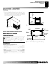
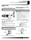
VENTING INSTALLATION
Continued
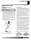
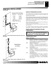
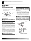
1. Determine the route your vertical venting will take. If ceiling
joists, roof rafters, or other framing will obstruct the venting
system, consider an offset (see Figure 24) to avoid cutting
loadbearing members.
Note:
Pay special attention to these in-
stallation instructions for required clearances (air space) to com-
bustibles when passing through ceilings, walls, roofs, enclo-
sures, attic rafters, etc. Do not pack air spaces with insulation.
Also note maximum vertical rise of the venting system and
any maximum horizontal offset limitations. Offsets must fall
within the parameters shown in Figure 13 on page 8.
2. Set the fireplace in desired location. Drop a plumb line down
from the ceiling to the position of the fireplace exit flue. Mark
the center point where the vent will penetrate the ceiling. Drill
a small locating hole at this point.
Drop a plumb line from the inside of the roof to the locating
hole in the ceiling. Mark the center point where the vent will
penetrate the roof. Drill a small locating hole at this point.
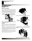
INSTALLATION FOR VERTICAL
TERMINATION
NOTICE: Use rigid pipe only. Flex venting is not to be
used with a vertical termination.
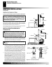
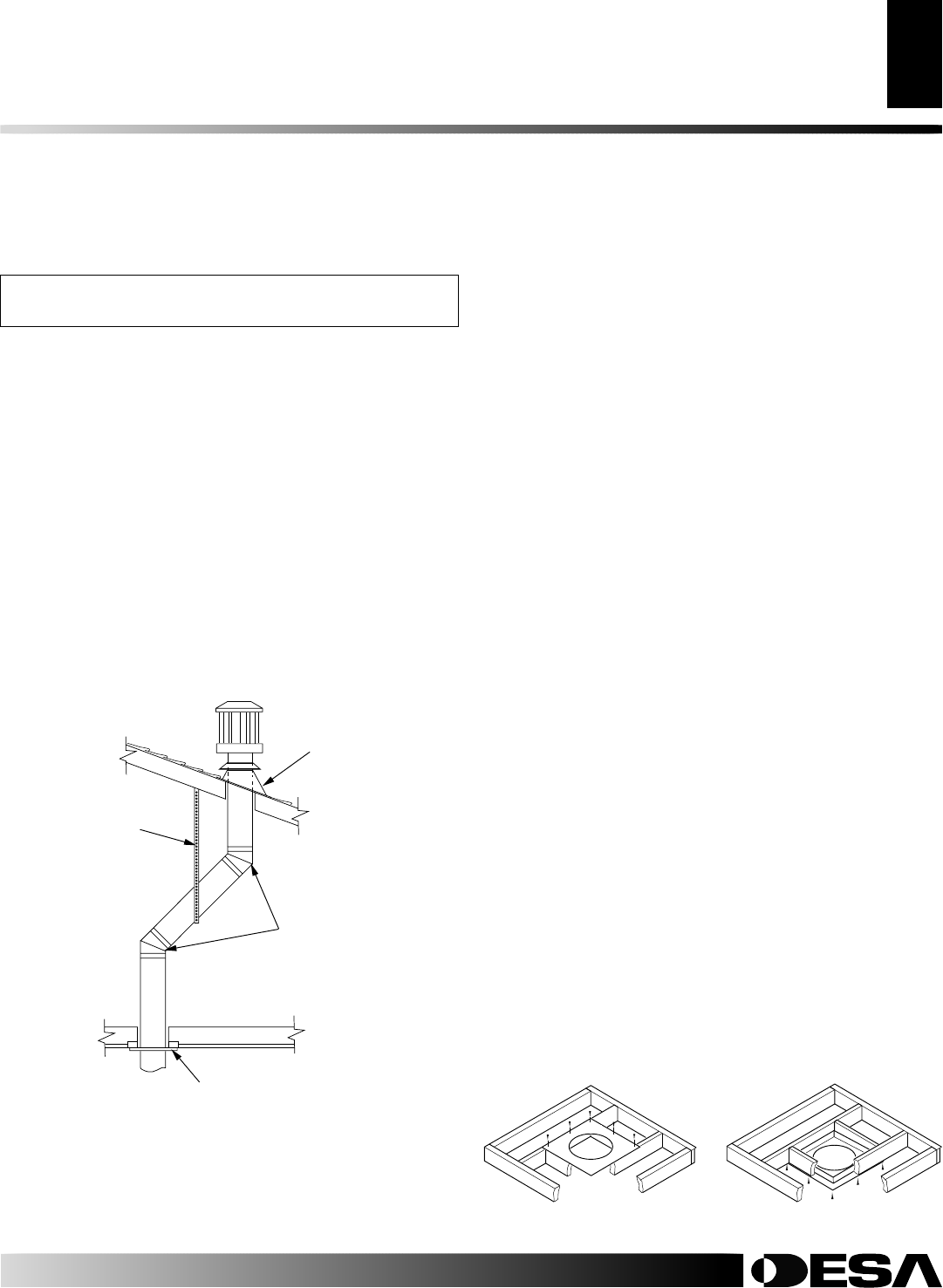
Figure 24 - Offset with Wall Strap and 45° Elbows
45° Elbow
Wall Strap
Roof
Flashing
Ceiling Firestop
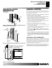
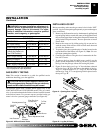
VENTING INSTALLATION
Installation for Vertical Termination
Flat Ceiling Installation
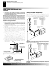
1. Cut a 10" square hole in the ceiling using the locating hole as a
center point. The opening should be framed to 10"x10" (254mm
x 254mm) inside dimensions, as shown in Figure 17 on page 11
using framing lumber the same size as the ceiling joists. If the
area above the ceiling is an insulated ceiling or a room, nail
firestop from the top side. This prevents loose insulation from
falling into the required clearance space. Otherwise, install
firestop below the framed hole. The firestop should be installed
with no less than three nails per side (see Figure 25).
2. Assemble the desired lengths of pipe and elbows necessary to
reach from the fireplace flue up through the firestop. All con-
nections must be sealed with high temperature silicone sealant
as specified in the second warning statement on page 9. Be
sure all pipe and elbow connections are fully twist-locked (see
Figure 16, page 10).
3. Cut a hole in the roof using the locating hole as a center point.
(Cover any exposed open vent pipes before cutting hole in
roof.) The 10"x10" hole must be measured on the horizontal;
actual length may be larger depending on the pitch of the roof.
There must be a 1" clearance from the vent pipe to combustible
materials. Frame the opening as shown in Figure 17 on page 11.
4. Connect a section of pipe and extend up through the hole.
Note:
If an offset is needed to avoid obstructions, you must
support the vent pipe every 3 feet. Use wall straps for this
purpose (see Figure 24). Whenever possible, use 45° elbows
instead of 90° elbows. The 45° elbow offers less restriction to
the flow of the flue gases and intake air.
5. Place the flashing over the pipe section(s) extending through
the roof. Secure the base of the flashing to the roof and framing
with roofing nails. Be sure roofing material overlaps the top
edge of the flashing as shown in Figure 24. There must be a 1"
clearance from the vent pipe to combustible materials.
6. Continue to add pipe sections until the height of the vent cap meets
the minimum building code requirements described in Figure 13,
page 8.
Note
: You must increase vent height for steep roof pitches.
Nearby trees, adjoining rooflines, steep pitched roofs, and other
similar factors may cause poor draft or down-drafting in high
winds. Increasing the vent height may solve this problem.
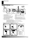
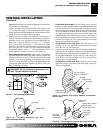
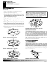
Figure 25 - Installing Firestop
If area above is not a room, install
firestop below framed hole.
If area above is a room, install
firestop above framed hole.