


Special offers from our partners!

Find Replacement BBQ Parts for 20,308 Models. Repair your BBQ today.
105706-01B
For more information, visit www.desatech.com
For more information, visit www.desatech.com
17
17
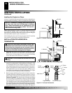
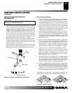
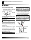
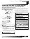
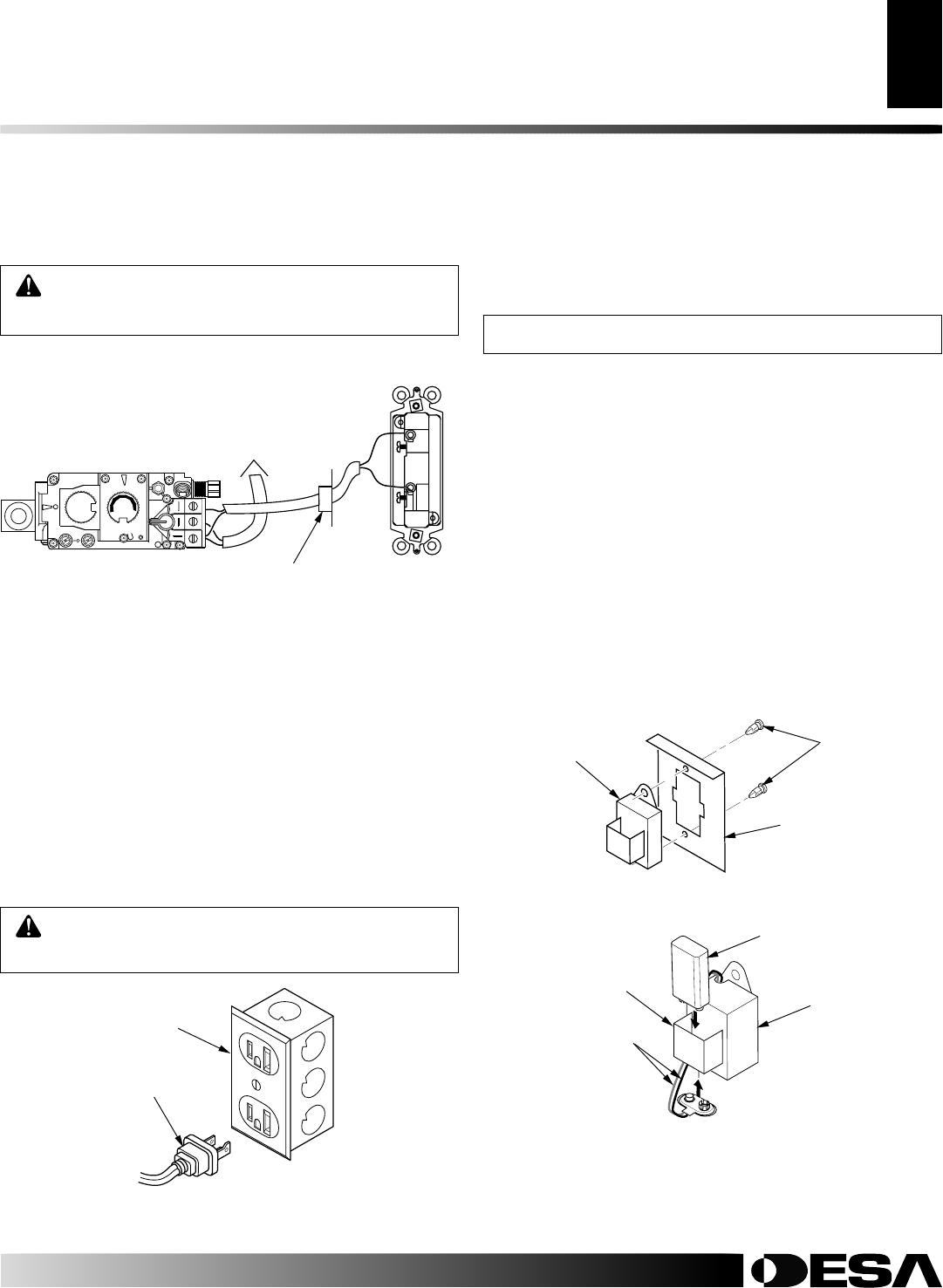
Figure 33 - Wall Switch Wiring Diagram
WARNING: Do not wire remote wall switch to main
power supply (Standard 120v household current).
Note:
If any of the original wire supplied must be replaced, use type
18 AWG-105 degree C (25 feet length MAXIMUM) or equivalent.
O
F
F
P
I
L
O
T
O
N
L
O
H
I
P
I
L
O
T
EA
16AI
7
TPTH TP TH
Wall Switch
(Supplied)
Route Millivolt Wires
(Supplied) Through Gas
Line Conduit Sleeve
To Thermopile
(Back View)
OPTIONAL WIRELESS HAND-HELD REMOTE
CONTROL INSTALLATION
Note:
If using an optional wireless hand-held remote control, the
wall switch is no longer operational.
NOTICE: Only use alkaline batteries (not included).
Installing Receiver
1. Remove access panel from lower front face of firebox. Lift
straight up on access panel until it stops. Pull bottom of access
panel forward, then down.
2. Disconnect wall switch wires from TH and TPTH terminals
on control valve (see Figure 33).
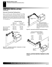
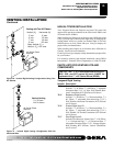
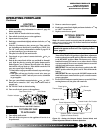
3. Install remote receiver unit onto mounting bracket using the
two plastic mounting clips (see Figure 35).
4. Connect wires to control valve. Connect white wire to termi-
nal TH. Connect red wire to terminal TPTH.
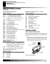
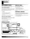
5. Locate the battery clip mounted on the back of the receiver
(see Figure 36).
6. Slide 9-volt battery (not included) through the clip.
7. Attach the terminal wires to the battery (see Figure 36).
8. Replace access panel. Place top of access panel into opening and
slide up. Push bottom of access panel in and slide down to install.
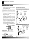
ELECTRICAL HOOKUP FOR BLOWER
ACCESSORY
Before blower accessory can be operated, it must be properly
connected to a standard 120 VAC power source. Refer to Wiring
Diagram on page 24.
An outlet box with two receptacles has been supplied for your
convenience, located on the lower left side of the appliance (see
Figure 34). An optional remote control may be installed at any time.
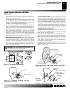
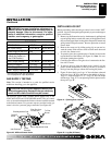
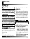
Figure 34 - Connecting Blower Accessory to Power Supply
For Optional
Fan Kit
From Blower
Assembly
CAUTION: Due to high temperatures, make sure
no wires are touching the bottom of the firebox.
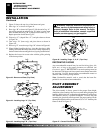
Figure 35 - Installing Remote Receiver (Shown from Rear of
Mounting Bracket)
Receiver
Mounting
Bracket
Plastic
Mounting
Clips
INSTALLATION
Wall Switch Installation (Cont.)
Electrical Hookup for Blower Accessory
Optional Wireless Hand-Held Remote Control (GHRC(TA) Series) Installation
2. Connect the 18 ga. wires from wall switch to the gas control
valve and microswitch, as shown in Figure 33.
INSTALLATION
Continued
Figure 36 - Installing Battery in Receiver
Battery Clip
9-Volt Battery
Receiver
Terminal Wires