


Special offers from our partners!

Find Replacement BBQ Parts for 20,308 Models. Repair your BBQ today.
www.desatech.com
116035-01E6
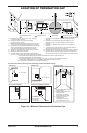
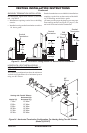
• If you plan on installing a television or enter-
tainment center recessed above your replace, it
is recommended that you maintain a minimum
18" above top of louver opening.
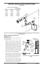
• When locating termination cap, it is important
to observe the minimum clearances shown in
Figure 7, page 8.
• If recessing into a wall, you can avoid extra
framing by positioning your replace against
an already existing framing member.
• Do not recess termination cap into a wall or
siding.
• You may paint the termination cap with 450ºF
(232ºC) heat-resistant paint to coordinate with
the exterior nish.
• There must not be any obstruction such as
bushes, garden sheds, fences, decks or util-
ity buildings within 24" from the front of the
termination cap.
• Do not locate termination cap where excessive
snow or ice build up may occur. Be sure to
clear vent termination area after snow falls to
prevent accidental blockage of venting system.
When using snow blowers, do not direct snow
towards vent termination area.
PRE-INSTALLATION
PREPARATION
Continued
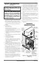
The (V)CD36R/T direct vent gas replace heater
is packaged with:
- one box containing a 4-log set located on the
burner in the rebox.
- one bag containing the owner’s manual with
installation instructions, operator’s guide, and
warranty information.
- one bag of glowing ember material.
- one bag of vermiculite hearth treatments.
Remove the shrink-wrap securing the 2 carton
trays to the unit. Lift the top carton tray off and
remove the four corner posts. Discard the bottom
tray once the unit is moved into position.
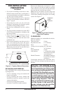
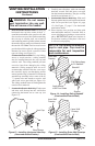
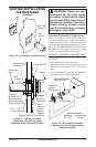
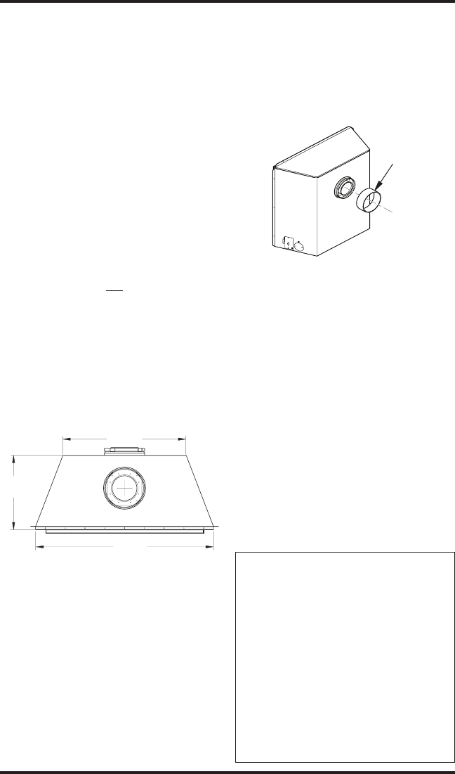
Note: On rear vent models you must remove the
berboard collar protector located on the rear
collar before installing the replace and venting
system. See Figure 4.
Figure 4 - Removing Collar Protector
(Rear Vent Fireplace)
Fireboard
Collar
Protector
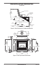
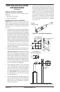
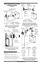
Figure 3 - Fireplace Bottom Dimensions
15"
(381 mm)
36"
(914 mm)
25"
(635 mm)
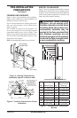
Minimum clearances to combustibles for the re-
place are as follows:
*Back and sides 0"/mm
Perpendicular walls 12" (305 mm)
Floor 0"/mm
Ceiling to louver opening 40" (1016 mm)
Front 36" (914 mm)
Top of Standoffs 0"/mm
Vent Surfaces 1" (26 mm) (See venting
instructions for specic
vent clearances.)
Mantel Clearances (See Mantel Clearances
for specics on mantel
clearances.)
Combustible material with a maximum thick-
ness of 5/8" may be ush with the top front of
replace.
-
-