


Special offers from our partners!

Find Replacement BBQ Parts for 20,308 Models. Repair your BBQ today.
www.desatech.com
116035-01E24
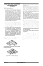
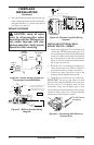
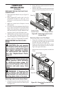
11. Peel off the backing paper and stick the sup-
plied wiring diagram decal on the rebox bot-
tom approximately 12" in front of the blower
(see Figure 38, page 23).
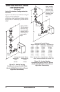
WIRING DIAGRAMS
-
FIREPLACE
INSTALLATION
Continued
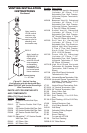
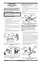
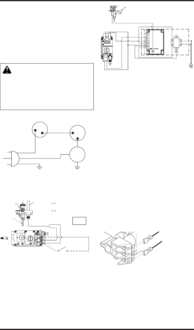
Figure 40 - Blower Wiring Diagram for
Thermostat-Controlled Models
Blue
Variable
Fan Switch
Fan Switch
(N.O.)
Green
White
On
110/115
V.A.C.
Blower
Motor
Black
Off
1
2
Black
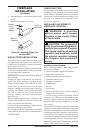
Figure 41 - Millivolt Ignition Wiring
Diagram
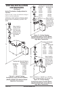
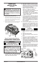
Figure 42 - Electronic Ignition Wiring
Diagram
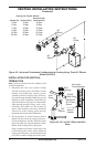
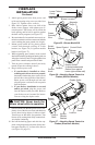
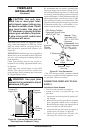
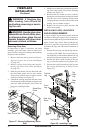
INSTALLING OPTIONAL WALL
1. Connect one terminal of 25 ft. wire for the wall
switch to the TPTH terminal on the valve. Con-
nect remaining wire terminal to the TH terminal
on the valve. Make sure that the wire terminals
are in the positions on the unit as pictured in
Figure 43. If wires are not connected as shown
the switch will not work.
2. Route the 25 ft. wire through openings pro-
vided on the sides of the burner system to a
convenient location to mount your switch.
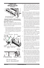
3. Connect one bare wire end to each of the
terminals of the GWMS2 wall switch.
4. Install the wall switch and cover in the wall.
IMPORTANT: Do not use any other wire than
that provided with the GWMS2 wall switch kit.
Do not exceed 15 ft. of distance from the valve
connection. Using wire of higher gage or turns
or exceeding the minimum distance will increase
resistance at the control valve causing unreliable
performance of the replace controls.
Figure 43 - Connecting Wall Switch to
Control Valve
To Wall Switch
Accessory
DO NOT
CONNECT
RED
REPLACE FACTORY WIRING WITH 105°C
EQUIVALENT OR HIGHER RATING
THERMOSTAT WIRE 18 GA. RED/WHITE
EXTERNAL WIRING USE ONLY CLASS 2
WHITE
TH/TP
TP
TH
WALL SWITCH
TO 120V
THERMOPILE
PILOT
BURNER
IGNITOR
LINE
PILOT GAS
O
F
F
P
I
L
O
T
O
N
PILOT SAFETY VALVE
MAIN GAS
INCOMING
SUPPLY
EV2
EV1
Pilot
Burner
IGNITOR LEAD
ORANGE
RED
BLACK
BLACK
BLACK
BLUE
GREEN
RED
BLUE
WHITE
BLACK
TRANSFORMER
GROUND
24 VAC
120 VAC
MODEL IS1070B
SYNETEK CONTROLS INC
GAS VALVE