


Special offers from our partners!

Find Replacement BBQ Parts for 20,308 Models. Repair your BBQ today.
www.desatech.com
116035-01E 23
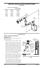
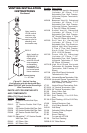
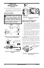
V
ar
ia
bl
e
F
a
n
Sw
it
c
h
W
hi
t
e
W
hi
te
Bl
a
c
k
Gr
e
en
On
11
0
/
1
1
5
V
.
A
.
C
.
Bl
o
w
e
r
M
o
t
o
r
B
l
a
c
k
B
l
ac
k
Bl
a
ck
Of
f
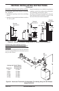
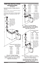
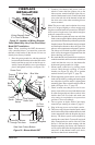
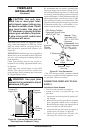
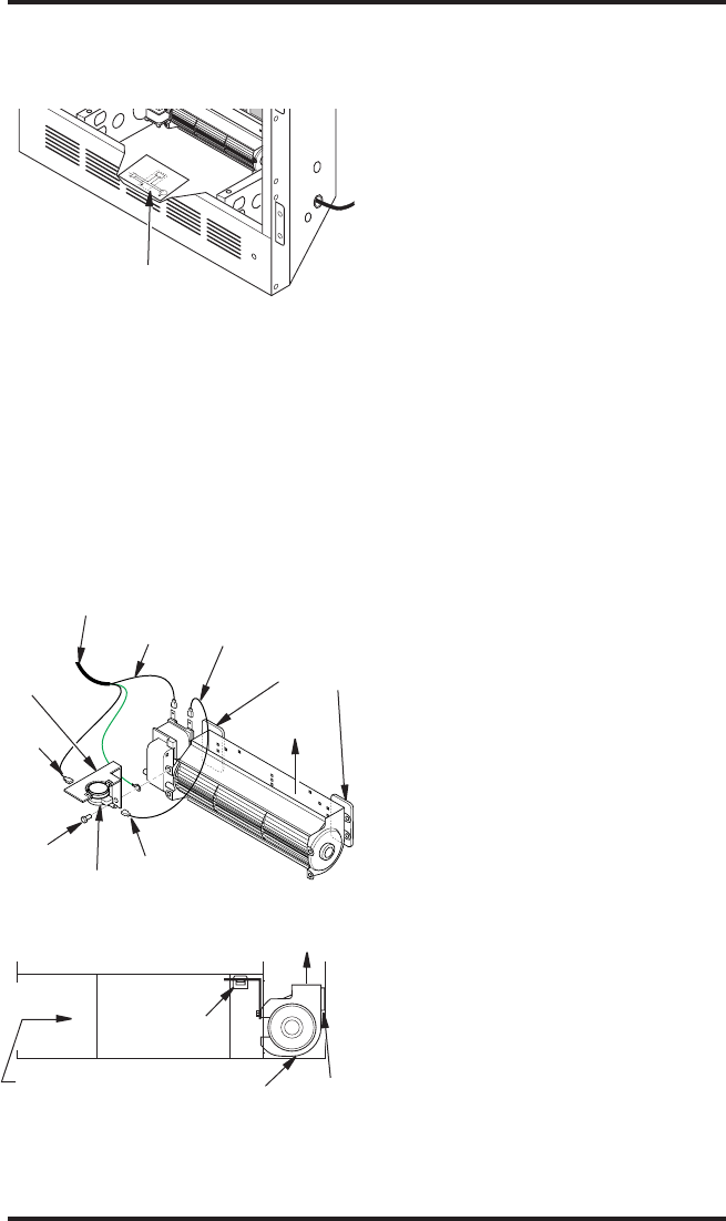
Figure 38 - Location of Wiring Diagram
Decal (Model May Vary From Illustration)
Wiring Diagram Decal
6" in Front of Blower
FIREPLACE
INSTALLATION
Continued
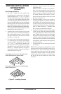
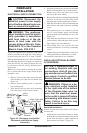
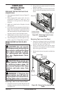
Note: When installing the BKT thermostati-
cally-controlled blower, you must rst secure the
thermal switch bracket to the blower if it has not
already been factory installed.
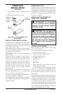
1. Place the green ground wire with ring terminal
between the bottom hole on the thermal switch
bracket and the top ear hole on the blower as-
sembly. Insert the phillips screw into all three
pieces and tighten securely (see Figure 39).
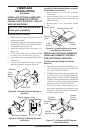
Thermodisc
Figure 39 - Blower Model BKT
Air Flow
Direction
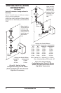
Route BKT Blower
Through This Area
Magnets
Blower
Location
Side View Firebox Bottom
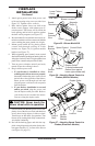
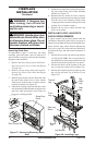
Black
Wire
Phillips
Screw
Blue Wire
Ring Terminal on
Green Wire
White Wire
Thermal
Switch
Thermal
Switch
Bracket
Power Cord
Air Flow
Direction
Magnetic
Strips
2. Connect wire harness and power cord ter-
minals. Connect the blue jumper wire to the
blower motor terminal and the right side ter-
minal of the thermal switch. Connect the black
wire to the left side of the thermal switch and
the white wire to the other remaining blower
motor terminal.
Note: The power cord outer insulation sleeve may
have to be stripped slightly to allow enough wire
length to reach and make all connections. DO NOT
trim excessive length away. Just enable enough to
make all connections securely.
3.
Place the blower against the lower rear wall of the
rebox outer wrapper with the exhaust port directed
upward and the thermodisc positioned up near the
replace bottom. The thermodisc must be oriented
near the replace bottom as shown in Figure 39 in
order to sense temperature and properly operate.
The blower will be held in position against the
back wall by the magnets incorporated onto the
blower housing (see Figure 39).
4. Be certain that all wire terminals are securely at-
tached to terminals on blower motor and thermal
switch and that the screw for the thermodisc
bracket and green ground wire is tight.
5. Mount speed control box by placing plastic
control shaft through opening in switch
bracket (see Figure 36, page 22) or ignition
module bracket (see Figure 37, page 22).
6. While supporting speed control, secure control
shaft with lock nut by pushing and turning lock
nut with pliers clockwise until it is tight against
mounting plate. Place control knob provided on
shaft (see Figure 36 or 37, page 22).
7. Check to make sure that power cord is com-
pletely clear of blower wheel and that there are
no other foreign objects in blower wheel. Also
double check all wire leads and make sure
wire routing is not pinched or in a precarious
position. Correct accordingly.
8. Turn on power to duplex outlet if previously
turned off per warning in column 2, page 21.
9. Plug in blower power cord to duplex outlet.
10. The blower will only run when the speed control
knob is in the ON position and the thermal switch
senses temperature after the replace begins to
heat up. The blower speed can be adjusted by
rotating the control knob. To turn off, turn knob
fully counterclockwise until it clicks off. If the
blower is ON and has been running with the
replace operating, the blower will continue to
run for a short time after the replace has been
turned off. As the thermal switch cools down,
the blower shuts down automatically.