


Special offers from our partners!

Find Replacement BBQ Parts for 20,308 Models. Repair your BBQ today.

www.desatech.com
116035-01E30
FIREPLACE
INSTALLATION
Continued
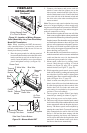
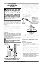
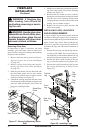
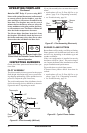
Figure 57 - Removing/Replacing Glass
Door
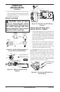
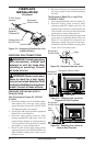
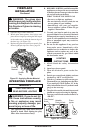
Figure 58 - Installing Logs
Top Left
Log
Front
Log
Top
Right
Log
Rear
Log
Rear Log
Stand
Log Mounts
Burner
Pan
Latch
UNLOCK
LOCK
Door Frame Tab
Glass Door
Panel
-
If replacement of glass is necessary, the entire
assembly, glass and frame, must be replaced. If
glass is broken, wear gloves and tape the remaining
fragments onto the frame.
1. Remove the lower louver panel (see Remov-
ing Lower Louver Access Panel and Figure
55, page 29).
2. Remove the top louver trim panel (see Re-
moving Top Louver Trim Panel and Figure
56, page 29).
3. Hold the glass frame with one hand and with
the other hand unlock the two door latches
found on top of the rebox to release tension
on the door frame (see Figure 57).
4. Unhook the locking clasp from the tabs on the
door frame and with both hands swing the door
panel out while pivoting the lower frame on
the lower retaining bracket.
5. Lift the lower frame tabs out from the position-
ing slots found on the lower frame retaining
bracket (see Figure 57).
6. Remount the new frame in reverse order by
placing the positioning tabs on the glass frame
into the slots in the retaining bracket then
swinging the door into the sealed position and
locking the two latches in place.
7. Replace the top louver panel and then the
lower louver panel.
A 4 piece ceramic log set comes packed inside the
unit rebox. Removal of glass door is necessary to
unpack and assemble the logs and add hearth treat-
ments. Follow steps under Removing/Replacing
Glass Door, page 29 to access the logs and burner.
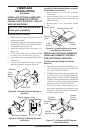
Assemble the logs and add burner treatments as
follows:
1. Position the base log onto burner log mounts.
(see Figure 58). Note: The cut out on the bot-
tom should t over the mounts and the base log
should be positioned against the rear panel
2. Position the holes on the bottom of the rear
log over the pins on the base log Figure 58).
3. Position the top left log and top right log onto
the rear log and base log as shown in (see
Figure 58).