


Special offers from our partners!

Find Replacement BBQ Parts for 20,308 Models. Repair your BBQ today.
www.desatech.com
116035-01E 21
FIREPLACE
INSTALLATION
Disconnect the
-
WARNING:
-
-
sence of local code, with the
current National Electric Code,
ANSI/NFPA 70, or the Canadian
Electric Code, CSA C22.1
A pre-wired junction box receptacle with strain
relief is provided on the right side of the cabinet
for hard wiring the unit to a 15 Amp, 120VAC,
60Hz grounded branch circuit. If the installation
demands that the electrical supply be connected
from the left side, the entire receptacle box can
be relocated to the left side by following these
instructions:
Note: If you do not need to relocate the junction
box, to connect the electric supply follow steps 8
through 11 only:
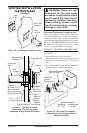
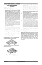
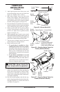
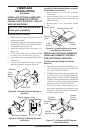
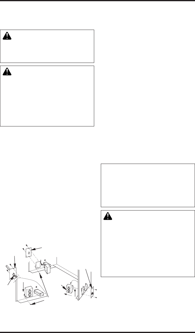
1. Remove 2 screws and outer cover with strain
relief bushing on right side of cabinet (see
Figure 34).
2. Remove inner retaining screw on junction
box mounting tab.
3. Slide junction box up until screw mounting
tab is lined up to notch in outer cabinet.
4. Swing the junction box out and slip retaining
ange out through the slot in outer cabinet.
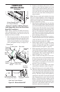
5. Remove two screws and outer cover on the
left side of the outer cabinet.
6. Reinsert junction box retaining ange through
slot now on the left side and swing screw
mounting tab back through notch as before.
7. Slide the junction box down till mounting tab
holes line up and replace the inner retaining
screw.
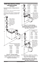
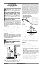
8. With junction box cover removed, pull the
end of 3-wire Romex supply line through
universal strain relief bushing on cover. (see
Figure 34).
9. Strip back the outer Romex to about 4" and
connect black, white and green wires accord-
ingly using 3 wire nut connectors.
10. Tuck tailing wires into junction box and
replace junction box cover using 2 remaining
screws.
11. Tighten down strain adjustment on universal
bushing until Romex sheathing is secured.
The electrical connection is now complete.
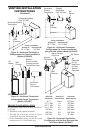
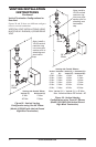
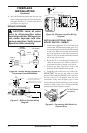
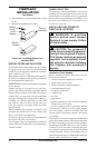
Figure 34 - Relocating Junction Box
Receptacle and Electrical Supply
Connection
J-Box Cover
with Strain
Relilef
J-Box
Cover
Romex
Cable
J-Box with
Receptacle
J-Box Cover with
Strain Relief
Screw/Tab
Retainer
-
WARNING: If there is a du-
-
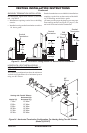
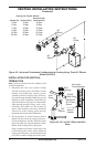
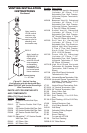
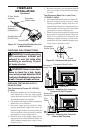
Follow all instructions provided in the blower
accessory kit.
1. Attach power cord to blower motor by rmly
pushing the two female terminals at the end of
power cord onto the two spade terminals on
blower motor (see Figure 35, page 22).