


Special offers from our partners!

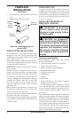
Find Replacement BBQ Parts for 20,308 Models. Repair your BBQ today.

www.desatech.com
116035-01E22
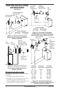
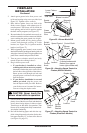
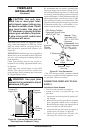
Blower Location
Side View
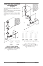
Figure 35 - Blower Model BK
Magnetic
Strips
Exhaust Port
Screw
Green
Ground
Wire
Spade
Terminals
Lower Firebox
Cavity
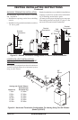
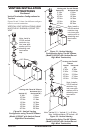
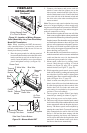
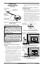
Figure 36 - Attaching Speed Control to
Firebox (Millivolt Models)
Speed Control
Control Shaft
Locknut
Control
Knob
Switch
Bracket
Blower
Plug-In
Duplex Outlet
(Located underneath
rebox oor against
lower right outside wall)
2. Attach green ground wire from power cord
to blower housing using screw provided (see
Figure 35). Tighten screws securely.
3. Place blower against lower rear wall of the
rebox outer wrapper with exhaust port di-
rected upward. The blower will t inside the
back opening and be held in position against
the back wall by magnets (see Figure 35).
4.
Be certain that all wire terminals are securely at-
tached to terminals on blower motor and that the
screw retaining the green ground wire is tight.
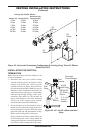
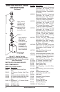
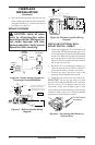
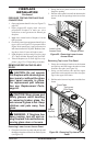
5. Mount speed control box by placing plastic
control shaft through opening in switch
bracket (see Figure 36) or ignition module
bracket (see Figure 37).
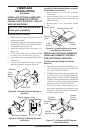
6.
While supporting speed control, secure control
shaft with lock nut by pushing and turning lock nut
with pliers clockwise until it is tight against front
panel. Place control knob provided on shaft.
7. Turn on power to duplex outlet if previously
turned off per the warning in above.
8. Plug in blower power cord.
a. Ifyourreboxisinstalledasafree-
standing unit with an accessory mantel,
determine whether the power cord will exit
the left side or the right side of the rebox.
Route power cord through exit hole and
plug the power cord into a wall receptacle
near the rebox.
b. Ifyourreboxinstallationisrecessed
and/or pre-wired, plug the power cord
into the duplex outlet provided. Refer to
your rebox owner’s manual for instruc-
tions on wiring the duplex outlet.
9. Check to make sure that the power cord is com-
pletely clear of the blower wheel and that there
are no other foreign objects in blower wheel.
Turn blower on and check for operation. Turn
blower off by turning knob fully counterclock-
wise before continuing.
10. Peel off the backing paper and stick the sup-
plied wiring diagram decal on the rebox bot-
tom approximately 12" in front of the blower
(see Figure 38, page 23).
Figure 37 - Attaching Speed Control to
Firebox (Electronic Models)
Duplex Outlet
Control
Knob
Locknut
Ignition
Module
Bracket
Speed
Control
Control
Shaft
FIREPLACE
INSTALLATION
Continued