


Special offers from our partners!

Find Replacement BBQ Parts for 20,308 Models. Repair your BBQ today.
www.desatech.com
116035-01E16
T
O
H
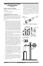
VENTING INSTALLATION INSTRUCTIONS
Continued
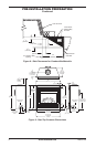
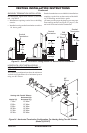
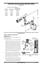
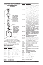
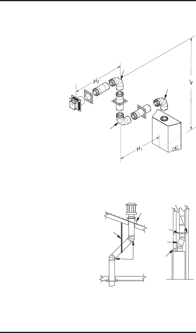
Figure 25 - Horizontal Termination Conguration for Venting Using Three 90° Elbows
(Model (V)CD36T)
TERMINATION
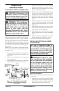
Note: Vertical restrictor must be installed in all
vertical installations.
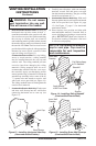
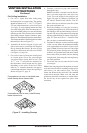
1. Determine the route your vertical venting
will take. If ceiling joists, roof rafters or other
framing will obstruct the venting system,
consider an offset (see Figure 26) to avoid cut-
ting load bearing members. Note: Pay special
attention to these installation instructions for
required clearances (air space) to combustibles
when passing through ceilings, walls, roofs,
enclosures, attic rafters, etc. Do not pack air
spaces with insulation. Also note maximum
vertical rise of the venting system and any
maximum horizontal offset limitations.
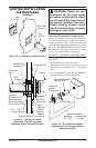
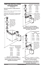
2. Set the replace in desired location. Drop a
plumb line down from the ceiling to the posi-
tion of the replace exit ue. Mark the center
point where the vent will penetrate the ceiling.
Drill a small locating hole at this point.
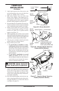
Drop a plumb line from the inside of the roof
to the locating hole in the ceiling. Mark the
center point where the vent will penetrate the
roof. Drill a small locating hole at this point.
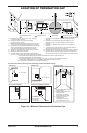
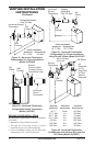
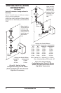
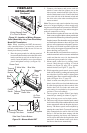
Figure 26 - 45° and 30° Offset with Wall
Strap
Horizontal (H
2
5' Min. 2' Max. 6' Max
6' Min. 3' Max. 8' Max
7' Min. 4' Max. 10' Max
8' Min. 5' Max. 12' Max
12' Min. 8' Max. 20' Max
20' Min. 8' Max. 20' Max
90°
Elbow
90°
Elbow
90°
Elbow
Roof
Flashing
Wall
Strap
45°
Elbows
WS-58
Wall Strap
2 - 2 x 4
Vertical
Header
OSR58-30
30° Offset
Return
Horizontal
Frame Member