


Special offers from our partners!

Find Replacement BBQ Parts for 20,308 Models. Repair your BBQ today.
115603-01A
8
For more information, visit www.desatech.com
For more information, visit www.desatech.com
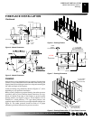
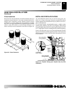
GAS LINE INSTALLATION
Continued
VENTING INSTALLATION
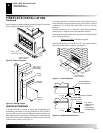
CHIMNEY PIPE INSTALLATION
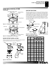
The DESA chimney system is a snap-lock, double wall pipe. It
consists
of a stainless steel inner flue pipe(s), a galvanized outer
pipe, and a wire spacer.
Each
section of pipe comes in lengths of 12, 18, 36, and 48 inches,
but the actual lineal gain for each is measured after each section is
fully connected. Lineal gain is the actual measurable length of a part
after two or
more parts are connected.
MODEL NO. DESCRIPTION GAIN
V3612ST See-Through" 52
3
/4"
Fireplace
48-12DM/48-12TM Flue Pipe 46
5
/8"
36-12DM/48-12TM Flue Pipe 34
5
/8"
STL-12D Chase Style 1" to 12"
Termination
RTL-12D Round Top Termination 7"
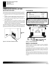
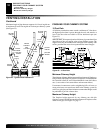
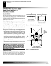
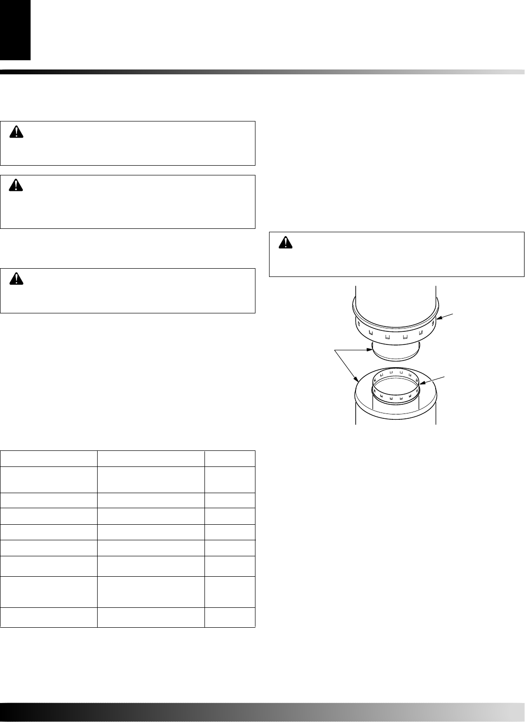
PIPE INSTALLATION
Place pipe assembly (inner and outer with wire spacer) over starter
collar.
Inner pipe(s) fit inside inner pipe(s). Outer pipe fits outside
outer pipe.
Be
gin by aligning hemmed end of inner flue pipe into the inner starting
flue pipe of fireplace. Push down until hem “snap-locks” with lances. The
ou
ter pipe is just the opposite, the female end has the lances. Continue the
same
procedure for the outer pipe (see Figure 16). It is important to assure
the joints between the chimney sections are fully locked. Check by pulling
chim
ney
upward after locking pipe hem(s). The chimney should not
come apart if properly locked. It is not necessary to add screws to keep
vertical or angled chimney runs toget
her
.
Figure 16 - Pipe Connection
WARNING: The opening around the starter collar on
top
of the fireplace must never be obstructed. Never use
blown insulation to fill the chimney enclosure.
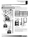
FIRESTOP SPACERS
Firestop spacers are required at each point where the chimney
penetrates
a floor or ceiling joist space. Their purpose is twofold.
They
establish and maintain the required clearance between the
outer
pipe and combustible materials, they also serve as a shield
between floors as required by most codes.
When penetrating a floor or ceiling at an angle, use firestop spacer
num
ber 30 FS-10D (see Replacement and Accessory Parts,
back page).
When
the pipe passes through a framed opening into a living space
above,
a firestop must be placed on the ceiling below (see Figure 17,
page
9). When the pipe passes through a framed opening into an attic
space
above, a firestop must be placed on the attic floor above (see
Figure 18, page 9).
CAUTION: When using a decorative appliance,
the
damper must be removed or permanently locked
in the open position.
WARNING: After ensuring that the gas valve is ON,
test
all gas piping and connections for leaks after
installing or servicing. Correct all leaks at o
nce.
WARNING: Never use an open flame to check for
a leak. Apply a noncorrosive leak detection fluid to
all
joints. Bubbles forming show a leak. Correct all
le
aks at once.
GASLINE INSTALLATION
CHIMNEY PIPE INSTALLATION
PIPE INSTALLATION
FI
REST OP SPACERS
15" (381mm)
Galvanized
Outer
Pipe
12 3/8" (314mm)
Stainless
Inner
Pipe
Lanced
Side
Up
Hemmed
Ends
Note:
An appropriate DESA hood (see Replacement and Accessory
Pa
rts, page 16) must be installed when using an unvented gas log set.
24-12DM/48-12TM Flue Pipe 22
5
/8"
18-12DM/48-12TM Flue Pipe 16
5
/8"
12-12DM/48-12TM Flue Pipe 10
5
/8"