


Special offers from our partners!

Find Replacement BBQ Parts for 20,308 Models. Repair your BBQ today.
115603-01A
7
7
For more information, visit www.desatech.com
For more information, visit www.desatech.com
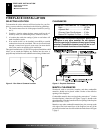
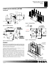
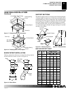
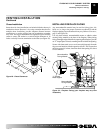
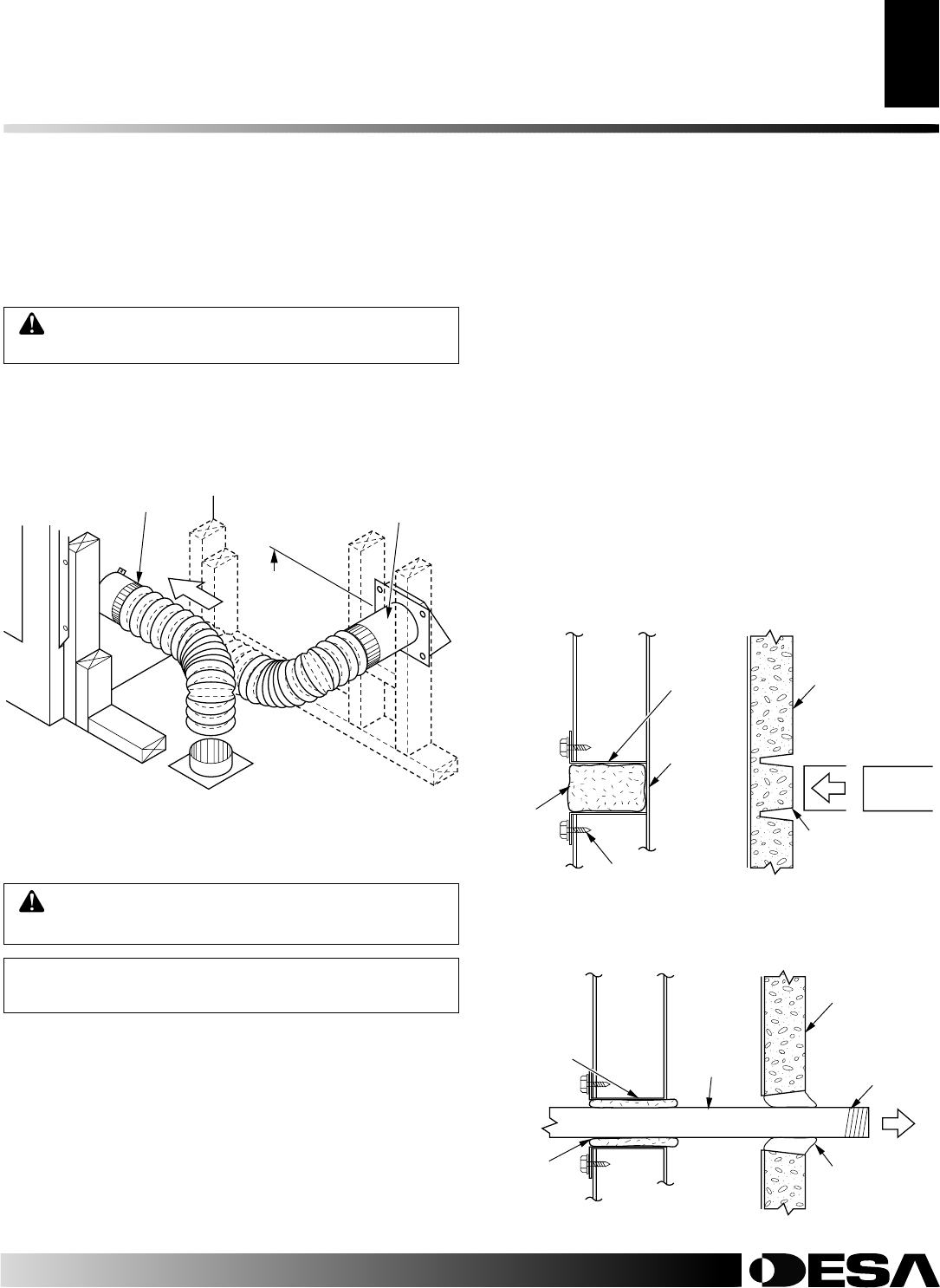
OUTSIDE AIR KIT
INSTALLATION
The installation of the outside air kit must be installed during the
rough framing of the fireplace due to the nature of its location.
Outside combustion air can be accessed through an exterior wall or
a vented crawl space (see Figure 13).
CAUTION: Air inlet ducts must not terminate in
attic space.
The maximum height for the air inlet above the platform of fireplace
is a minimum of 3 feet below the chimney cap.
For further details on the installation of the outside air kit, please
refer to the instructions included with the air kit.
Figure 13 - Air Kit Installation
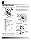
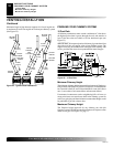
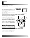
Figure 14 - Removing Knockout for Gas Line Installation
FOR UNVENTED ROOM HEATERS, ANSI\IAS\AGA Z21.11.2,
ARE TO BE INSTALLED IN THIS FIREPLACE.
1. To install, remove the knockout indentation on the refractor
(or firebrick) wall located approximately 2 inches above the
refractory hearth floor. The knockout indentation must be firmly
tapped with any solid object until it is released. Remove frag-
mented portion of refractory (see Figure 14).
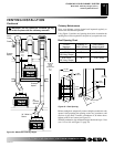
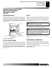
2. Remove gas line cover plate on rear of fireplace and pull out insu-
lation from gas line conduit sleeve, save insulation for reuse.
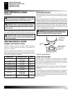
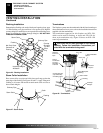
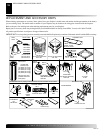
3. Run gas line into the fireplace through the rear at 11
1
/4" from
the floor and through gas line conduit sleeve (if using a raised
platform, add height). Provide sufficient gas line into fireplace
chamber for fitting connection (see Figure 15).
Note:
Secure incoming gas line to wood framing to provide rigidity
for threaded end.
4. Repack insulation around gas line and into sleeves openings.
Seal any gaps between gas line and refractory knockout hole
with refractory cement or commercial furnace cement. Install
the decorative gas appliance or cap off gas line if desired.
OUTSIDE AIR KIT INSTALLATION
GAS LINE INSTALLATION
Air Inlet
Location
Must Allow
For Bushes
Or Snow
Air Inlet
Termination
GAS LINE INSTALLATION
WARNING: A qualified service person must con-
nect fireplace to gas supply. Follow all local codes.
NOTICE: BEFORE YOU PROCEED, MAKE SURE
YOUR GAS SUPPLY IS OFF!
A gas line may be installed for the purpose of installing a vented or
vent-free decorative gas appliance available through your local
distributor. Use only gas piping approved by local codes. When
installing a gas line, a shutoff valve designed for installation outside
the appliance is recommended.
The gas pipe is intended for connection to a decorative gas appliances
that operate from natural or propane/LP fuel only: (1), incorporating
an automatic shutoff device and, (2), complying with the Standard for
Decorative Gas Appliances for Installation in Vented Fireplace,
ANSI Z21.60-1990. ONLY UNVENTED GAS LOG SETS WHICH
HAVE BEEN FOUND TO COMPLY WITH THE STANDARD
Secure Two Collars With
Duct Tape or Screws
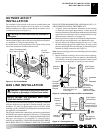
Figure 15 - Running Gas Line
Outside of
Fireplace
Gas Line
Conduit
Remove
Insulation
Temporarily
(Do Not
Discard)
Remove
Knockout
Replace Screws After
Removing Gas Line
Cover Plate
Side Firebrick
Finished Side
Refractory
Knockout Plug,
Remove by
Tapping Lightly
With A 1/2" Dowel
Outside of
Fireplace
Side Firebrick
Finished Side
Incoming
1/2" Black
Iron Pipe
Gas Line
Conduit
Repack
Insulation
Seal Opening
With Refractory
Cement
Provide Enough
Threaded End For
Fitting Connection