


Special offers from our partners!

Find Replacement BBQ Parts for 20,308 Models. Repair your BBQ today.
www.desatech.com
111044-01F
17
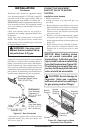
Installation must include an equipment shutoff
valve, union and plugged 1/8" NPT tap. Locate NPT
tap within reach for test gauge hook up. NPT tap
must be upstream from fireplace (see Figure 24).
IMPORTANT: Install an equipment shutoff valve
in an accessible location. The equipment shutoff
valve is for turning on and shutting off the gas to
the appliance.
Check your building codes for any special re
-
quirements for locating equipment shutoff valve
to fireplaces.
Apply pipe joint sealant lightly to male NPT
threads. This will prevent excess sealant from
going into pipe. Excess sealant in pipe could result
in clogged fireplace valves.
WARNING: Use pipe joint
sealant that is resistant to liq
-
uid petroleum (LP) gas.
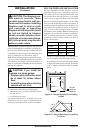
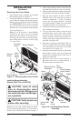
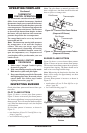
We recommend that you install a sediment trap in
supply line as shown in Figure 24. Locate sediment
trap where it is within reach for cleaning. Install in
piping system between fuel supply and fireplace.
Locate sediment trap where trapped matter is not
likely to freeze. A sediment trap traps moisture and
contaminants. This keeps them from going into fire
-
place controls. If sediment trap is not installed or is
installed wrong, fireplace may not run properly.
INSTALLATION
Continued
* Purchase the optional CSA design-certified
equipment shutoff valve from your dealer. See
Accessories, page 30.
Figure 24 - Gas Connection
CSA Design-Certified
Equipment Shutoff Valve
With 1/8" NPT Tap*
PROPANE/LP
From External
Regulator (11"
W.C. to 14" W.C.
Pressure)
NATURAL
From Gas Meter
(5" W.C. to 10.5"
W.C. Pressure)
3" Minimum
Pipe Cap Tee
Nipple Joint
Sediment Trap
CONNECTING EQUIPMENT
SHUTOFF VALVE TO HEATER
CONTROL
Installation Items Needed
• Phillips screwdriver
• sealant (resistant to propane/LP gas, not
provided)
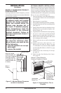
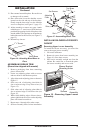
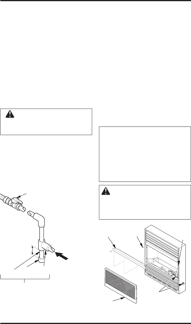
1. Remove fireplace screen. Remove two screws
that hold fireplace screen in place for shipping.
These screws are located near top of screen.
Discard screws. Lift fireplace screen up and
pull out to remove.
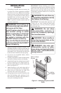
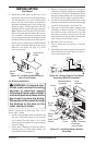
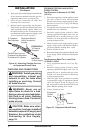
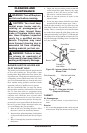
2. Remove screws that attach branch support
to fireplace (see Figure 25). Carefully lift up
branch support and remove from fireplace (see
Figure 25).
3. Route flexible gas line, included, from fire
-
place control to equipment shutoff valve
through side or rear access holes in outer
casing.
NOTICE: Most building codes
do not permit concealed gas
connections. A flexible gas line
is provided to allow accessibility
from the fireplace (see Figure 25).
The flexible gas supply line con-
nection to the equipment shutoff
valve should be accessible.
CAUTION: Avoid damage to
regulator. Hold gas regulator
with wrench when connecting it
to gas piping and/or fittings.
Figure 25 - Removing Log Base
Assembly From Fireplace
Branch
Support
Screen
Screen
Shipping
Screw
Shoulder
Screw
Flexible
Gas Line