


Special offers from our partners!

Find Replacement BBQ Parts for 20,308 Models. Repair your BBQ today.
www.desatech.com
111044-01F
12
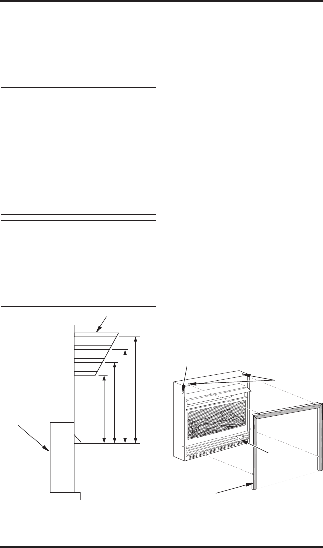
13"
16"
19"
21"
2
1
/
2
"
6"
8"
10"
Note:
A
ll vertical
measurements
are from top of
fireplace
opening to
bottom of
mantel shelf. All
measurements
are in inches.
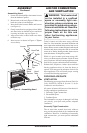
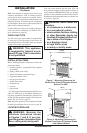
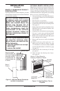
MANTEL CLEARANCES FOR BUILT-
IN INSTALLATION
If placing mantel above built-in fireplace, you must
meet minimum clearance between mantel shelf and
top of fireplace opening.
NOTICE: Surface temperatures
of adjacent walls and mantels
become hot during operation.
Walls and mantels above the
firebox may become hot to
the touch. If installed properly,
these temperatures meet the
requirement of the national
product standard. Follow all
minimum clearances shown in
this manual.
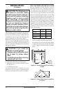
NOTICE: If your installation does
not meet the minimum clear-
ances shown, you must do one
of the following:
• raise the mantel to an accept-
able height
• remove the mantel
INSTALLATION
Continued
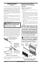
Figure 12 - Minimum Mantel Clearances
for Built-In Installation
Mantel Shelf
Note: All vertical
measurements are
from top of fireplace
opening to bottom
of mantel shelf. All
measurements are
in inches.
Side of
Firebox
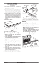
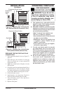
OPTIONAL MANTEL INSTALLATION
Note: Refer to instructions provided with the man-
tel for assembly instructions. Refer to instructions
below for system installation. Refer to instructions
on page 4 for firebox assembly. Blower accessory
should be installed if it is being used (see Installing
Blower Accessory GA3450T, page 13).
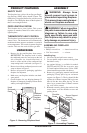
1. Unscrew four brass screws that attach top lou
-
ver to fireplace. Remove louver from fireplace
and set aside.
2. Place fireplace on wood base.
3. Place mantel around fireplace/base assembly.
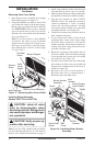
4. Assemble brass trim kit. See Assembling Brass
Trim
, page 13.
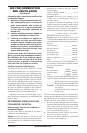
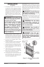
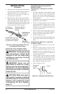
5. Firmly snap brass trim kit on shoulder screws.
Shoulder screws are located on fireplace cabi
-
net (see Figure 13).
6.
Align brass trim kit for flush fit around opening.
7.
Use two 3" wood screws provided and attach
fireplace base to wooden base (see Figure 13).
8. Remove brass trim kit and mantel. Be careful
not to damage wall or mantel.
9. Place wood base next to wall at installation
location.
10. Attach wood base to floor with two 1 3/4"
black screws provided (see Figure 14, page
13). If the floor is concrete use anchor method
(see Attaching Wood Base to Solid Floor, page
14, page 13).
11. Install gas line. See Connecting To Gas Sup
-
ply, page 16.
12. Check for leaks. See Checking Gas Connec
-
tions, page 18.
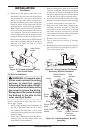
Shoulder
Screws
Assembled
Brass Trim
Hole for 3"
Wood Screw
for Attaching
Fireplace to
Wooden Base
Hole for 3" Wood Screw for
Attaching Fireplace to Mantel
Figure 13 - Attaching Brass Trim to
Fireplace