


Special offers from our partners!

Find Replacement BBQ Parts for 20,308 Models. Repair your BBQ today.
www.desatech.com
111044-01F
15
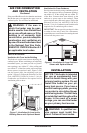
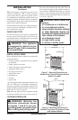
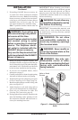
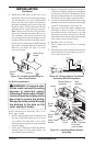
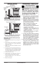
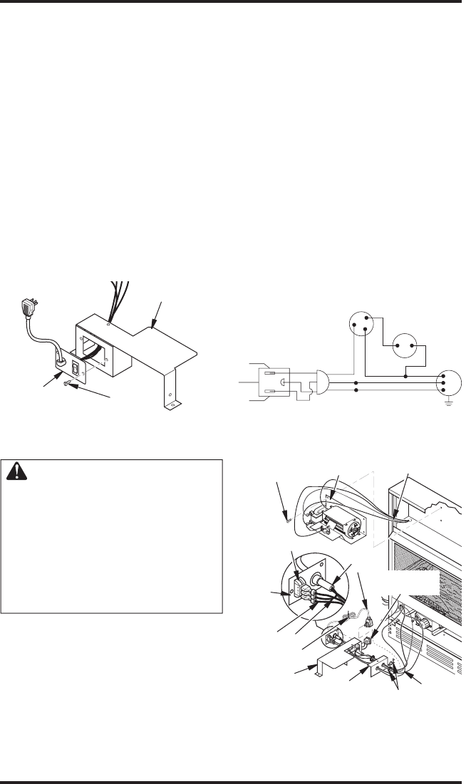
9. Install the switch plate on the valve cover
shield with 2 #10 screws provided (see Figure
19). Reinstall the valve cover shield. Route
power cord out of the cabinet by inserting it
through the bushing on the outer casing (see
Figure 18, page 14). Plug fan kit into 120-Volt
grounded power supply and test operation.
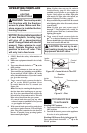
Note: When switch is in the AUTO position,
the fan will start after the heater has run for
a few moments. The fan will continue to run
for several moments after the heater has been
turned off. When switch is in the ON position,
the fan will run until turned to OFF. Reinstall
upper louver assembly and hood if previously
removed, (see Figure 16, page 13). Close
lower louver door.
INSTALLATION
Continued
Figure 19 - Installing Switch Plate to
Valve Cover Shield
Switch
Plate
Screw
Valve Cover
Shield
For Built-In Installation
WARNING: A licensed elec-
trician must connect the wiring
harness to electrical supply
following all local codes. Electri
-
cian must provide a clamp on the
box cover to secure the wiring.
Wiring should be routed through
the bushing in the hole on the
outer casing of heater.
Follow instructions in Removing Valve Cover
Shield, page 14, then
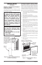
1. Install a snap bushing found in hardware kit
into one of the holes found on rear of valve
cover shield. The other hole is for a strain
relief clamp (not supplied) to secure incoming
electrical supply.
2. Follow steps 2 through 6 in Installing Blower
Assembly, page 14. Also remove black wire
from middle switch terminal 2.
3.
Remove black plastic strain relief and power
cord from switch plate. The power cord supplied
will not be used in built-in installations. Pop in
the plastic snap bushing found in hardware kit
into the hole left by supply cord/strain relief.
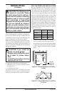
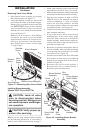
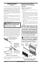
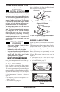
4. A licensed electrician must follow the wiring
diagram to connect incoming electrical supply
to fan kit wiring harness (see Figure 20).
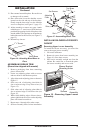
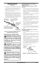
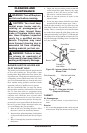
5. Plug power cord to the outlet receptacle (not
provided) as shown in Figure 21. Wind the
extra cable in power cord and tie it up with
the plastic wire strap (see Figure 21). Set the
cable bundle between the burner bracket and
outer casing, away from the burner.
6. Reinstall valve cover shield.
7. Test to make sure the blower is working
properly.
8. Reinstall upper louver assembly and hood if
previously removed, (see Figure 16, page 13).
Close lower louver door.
Figure 20 - Wiring Diagram For Blower
Accessory Built-In Installation
Red
Red
Fan Switch
(Auto/Off/On)
Blue
Blue
Thermostat
Switch
(N.O.)
Green
White
Green
White
On
11
0/115
V.
A.C.
Blower
Motor
Black
Of
f
1
2
3
Auto
Blower Bracket
Assembly
Screw
Wire
Harness
Power
Cord
Valve Cover
Shield
Box
Cover
Wire
Harness
Switch
Plate
Switch
Clamp
Connector
(not included)
Outlet
Receptacle
Blue
Red
Plastic Wire
Strap
Figure 21 - Installing Blower Bracket
Assembly