


Special offers from our partners!

Find Replacement BBQ Parts for 20,308 Models. Repair your BBQ today.
www.desatech.com
111044-01F
14
INSTALLATION
Continued
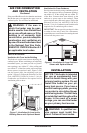
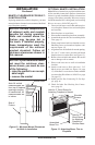
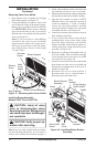
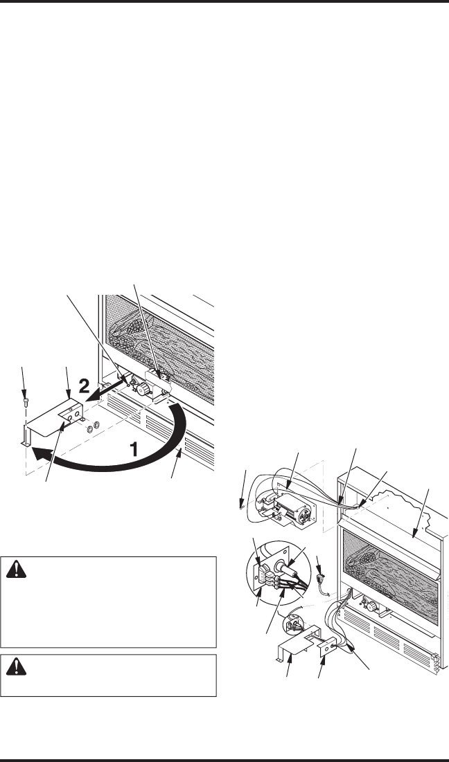
Removing Valve Cover Shield
1. Open bottom louver assembly by swinging
the assembly down (see Figure 17).
2. Using short Phillips screwdriver, remove the
screw under the center of the branch support.
Rotate valve cover shield clockwise and slide
out. IMPORTANT: Do not remove shoulder
screw on the left side of valve cover shield.
Slide the valve cover shield off of the shoulder
screw (see Figure 17).
Note: If you do not have a short Phillips
screwdriver, the screen, log set and branch
support must be removed so a longer screw
-
driver may be used. See Connecting Equip-
ment Shutoff Valve to Heater Control, page
17, steps 1 and 2.
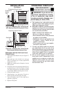
Remove
Screw
Valve
Cover
Shield
Shoulder
Screw
Figure 17 - Removing Valve Cover Shield
Branch Support
Snap Bushings
Bottom Louver Assembly
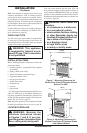
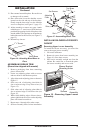
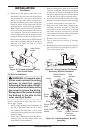
Installing Blower Assembly
(Models CGCFTP and CGCFTN)
CAUTION: Label all wires
prior to disconnection when
servicing controls. Wiring errors
can cause improper and danger-
ous operation.
CAUTION: Verify proper op-
eration after servicing.
Note: If you are using a mantel with your heater,
use the following instructions. If your heater is
built-in, see For Built-In Installation on page 15.
1. Install snap bushings found in hardware kit
into both holes in rear of valve cover shield.
2.
Make sure the wire harness is firmly connected to
the terminals on the blower bracket assembly.
3. Note the wire locations on back of AUTO/
OFF/ON switch. The terminals on back of
switch are numbered 1, 2 and 3. Carefully
remove red wire from terminal 1 and blue
wire from terminal 3. Black wire can remain
on middle terminal 2 (see Figure 18).
4. Carefully disconnect green and white wires at
their insulated connectors.
5. In top of the heater cabinet, locate the four
mounting holes on the outer casing. Align
these four holes with those on the blower
bracket assembly. Attach blower bracket as
-
sembly to the outer casing with 4 #10 screws
provided (see Figure 18).
6. Route the wire harness through the hole in
left side of baffle. Pull wire harness through
lower opening above where the valve shield
was removed. (see Figure 18).
7. Insert the 4 wire harness into one of the round
holes in the rear of the valve cover shield and
through the rectangular hole in the front of
shield (see Figure 18).
8. Reconnect red wire to switch position 3.
Reconnect blue wire to switch position 1.
Reconnect green and white wires.
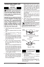
Figure 18 - Installing Blower Bracket
Assembly
Wire
Harness
Blower Bracket
Assembly
Screw
Power
Cord
Valve Cover
Shield
Box
Cover
Wire
Harness
Switch
Plate
Switch
Baffle
Wiring Routing
Hole in Baffle
Blue
Red