


Special offers from our partners!

Find Replacement BBQ Parts for 20,308 Models. Repair your BBQ today.
107032-01H
For more information, visit www.desatech.com
For more information, visit www.desatech.com
21
21
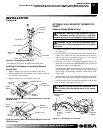
INSTALLATION
Continued
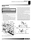
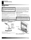
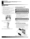
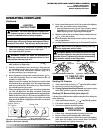
Figure 38 - Installing Remote Receiver
* Wire harness provided in the fireplace hardware pack.
Wires from
Valve
Wire Harness*
Black Wire
Red Wire
Red Wire
Black Wire
Remote
Receiver
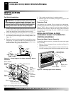
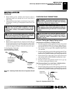
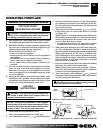
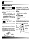
Installing 9-Volt Battery in Hand-Held Remote
Control Unit
1. Remove battery cover on back of remote control unit.
2. Attach terminal wires to the battery (not included). Place bat-
tery into the battery housing.
3. Replace battery cover onto remote control unit.
Figure 39 - Installing Battery in Hand-Held Remote Control Unit
(GHRCB Series)
Battery Cover
9-Volt
Battery
Terminal
Wires
Remote
Control Unit
Battery
Housing
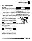
Figure 40 - Installing Battery in Hand-Held Remote Control Unit
(GHRCTB Series)
Remote
Control Unit
Battery Cover
Terminal Wires
9-Volt
Battery
Battery
Housing
OPTIONAL WALL MOUNTED THERMOSTAT -
GWMT1
(Remote-Ready Models Only)
WARNING: Do not connect this thermostat to any
electrical source! Electrical shock and/or fire hazard
will occur.
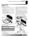
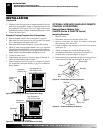
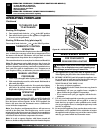
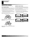
1.
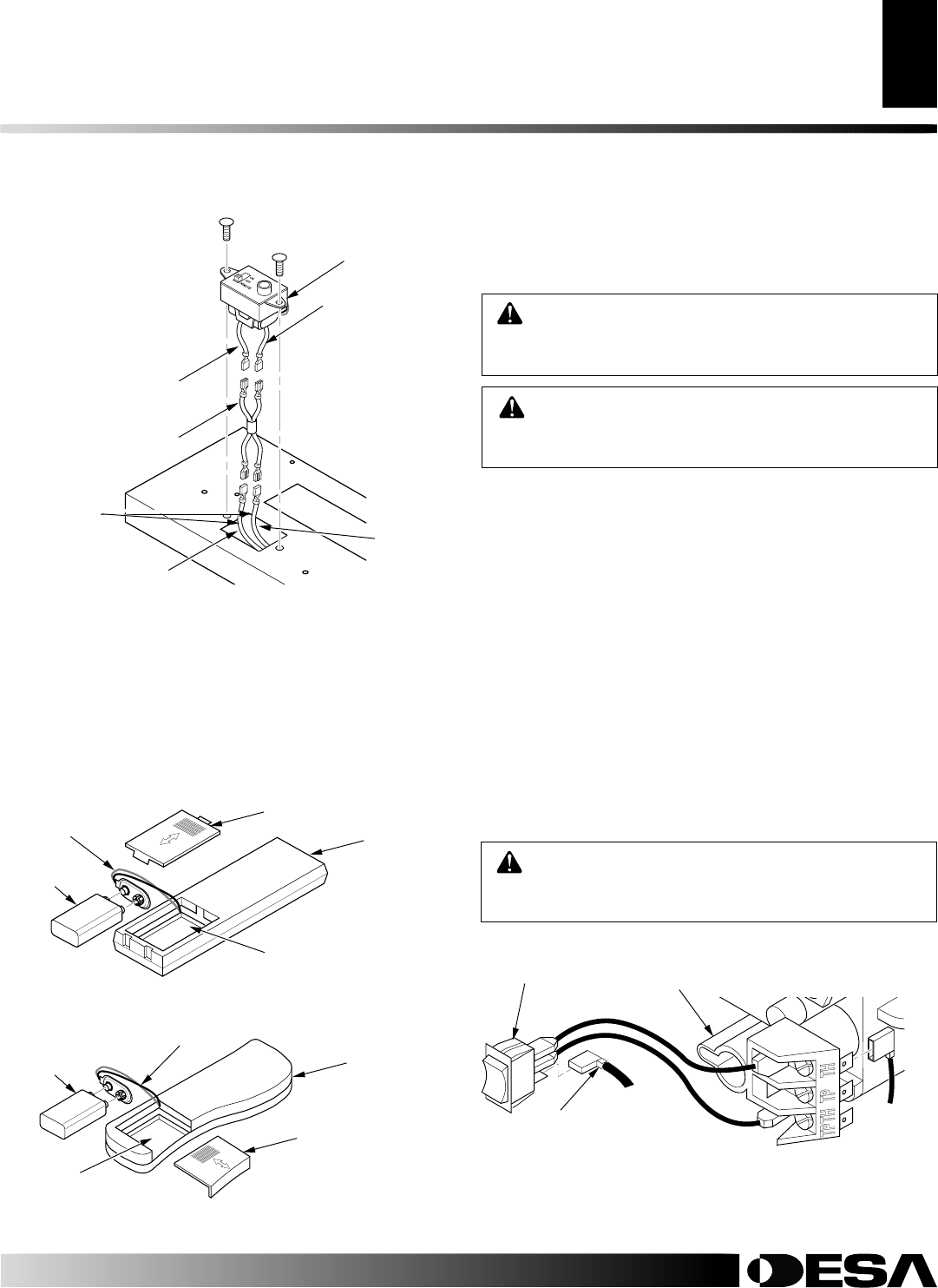
Connect one terminal of 25 ft. wire to bottom contact of switch
(see Figure 41).
2. Connect remaining wire terminal to the “TH” terminal on the
control valve. Make sure that wire terminals are in the posi-
tions on your unit as pictured in Figure 41. If wires are not
“crossed” the thermostat will not work.
3. Route the 25 ft. wire to a convenient location to mount your
thermostat (no outside wall).
IMPORTANT:
The wire may be
shortened but must not be lengthened.
The thermostat should be mounted 54" above the floor in a
location where there is good air circulation. Avoid heat sources
such as lamps, direct sunlight, fireplace, or heat and air condi-
tioning ducts.
4. Gently remove the cover of the thermostat from the base. Grasp
the sides of the cover firmly and pull to separate from the base.
5. Feed the electrical wires through the rectangular slots on each
side of the base (see Figure 42, page 22).
WARNING: Read and follow installation instruc-
tions. Installation should be done by a qualified
installer familiar with low-voltage wiring procedures.
Figure 41 - Connecting Wire Terminals
A
U
T
O
OFF
O
N
One
terminal
of 25 ft.
wire
Switch on Gas
Fireplace
To Wall
Thermostat
or Switch
To Wall
Thermostat
or Switch
Control
Valve
WARNING: Do not connect the thermostat to a
power source. Electrical shock and/or a fire hazard
will occur.
INSTALLATION
Optional Wireless Hand-Held Remote Control Accessories [Remote-Ready Models Only] (Cont.)
Optional Wall Mounted Thermostat - GWMT1 [Remote-Ready Models Only]