


Special offers from our partners!

Find Replacement BBQ Parts for 20,308 Models. Repair your BBQ today.
107032-01H
For more information, visit www.desatech.com
For more information, visit www.desatech.com
10
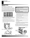
Actual Framing
Height 26" 26
7
/8"
Front Width 26
3
/4" 26
7
/8"
Depth 9
1
/2" 10
1
/2"
Bottom 3/4" 3/4"
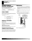
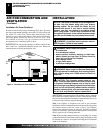
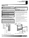
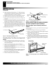
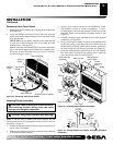
1. Frame in rough opening. Use dimensions shown in Figure 8 for
the rough opening. If installing in a corner, use dimensions
shown in Figure 9 for the rough opening. The height is 26
7
/8"
which is the same as the wall opening above.
2. If installing GA3450T blower accessory, do so at this time.
Follow instructions included with blower accessory.
Note:
If not installing blower accessory, you may wish to run
electrical wiring to your fireplace for future blower installa-
tion (see Accessories, pages 38 and 39). Use only approved
three-wire electrical wiring.
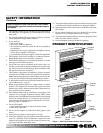
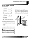
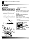
BUILT-IN FIREPLACE INSTALLATION
Built-in installation of this fireplace involves installing fireplace
into a framed-in enclosure. This makes the front of fireplace flush
with wall. An optional brass trim kit accessory is available (see
Accessories, pages 38 and 39). Brass trim will extend past sides of
fireplace approximately 1/2 inch. This will cover the rough edges of
the wall opening. If installing a built-in mantel above the fireplace,
you must follow the clearances shown in Figure 11, page 11. Follow
the instructions below to install the fireplace in this manner.
Note:
A qualified installer should make all electrical connections.
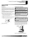
3. Install gas piping to fireplace location. This installation includes
an approved flexible gas line (if allowed by local codes) after
the equipment shutoff valve. The flexible gas line must be the
last item installed on the gas piping.
4. If you have not assembled firebox, follow instructions on page 5.
5. Carefully set fireplace in front of rough opening with back of
fireplace inside wall opening.
6. Attach flexible gas line to fireplace gas regulator. See Con-
necting Fireplace to Gas Supply, page 18.
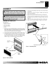
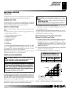
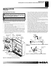
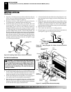
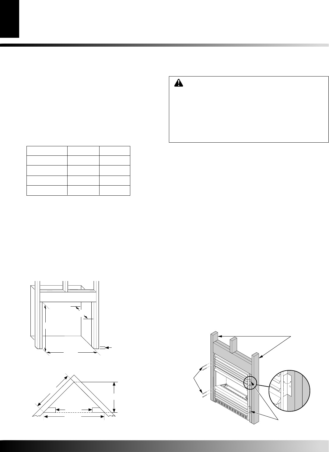
7. Bend four nailing flanges on outer casing with pliers (see
Figure 10).
8. Attach fireplace to wall studs using nails or wood screws
through holes in nailing flange.
9. Check all gas connections for leaks. See Checking Gas Con-
nections, page 19.
10. If using optional brass trim kit, install the trim after final fin-
ishing and/or painting of wall. See instructions included with
brass trim accessory for attaching brass trim.
IMPORTANT:
When finishing your firebox, combustible materials
such as wall board, gypsum board, sheet rock, drywall, plywood, etc.
may be butted up next to the sides and top edge of the firebox.
Combustible materials should never overlap the firebox front facing.
INSTALLATION
Continued
26
7
/
8
"
26
7
/
8
"
3/4" Off
The Floor
Minimum
10
1
/
2
"
Figure 9 - Rough Opening for Installing in Corner
Figure 8 - Rough Opening for Installing in Wall
36
5
/
8"
25
7
/
8"
51
3
/
4"
26
7
/
8"
Figure 10 - Attaching Fireplace to Wall Studs
WARNING: If pre-wiring, do not connect wiring to
any electrical source at this time.
Install fireplace electrical outlet and connect wiring
to outlet before connecting to electrical source. The
fireplace electrical outlet is included with the GA3450T
blower accessory.
Only use the fireplace electrical outlet supplied with
the GA3450T blower accessory.
Nailing
Flanges
Nails or
Wood
Screws
Wall Studs
INSTALLATION
Built-In Fireplace Installation