


Special offers from our partners!

Find Replacement BBQ Parts for 20,308 Models. Repair your BBQ today.

107032-01H
For more information, visit www.desatech.com
For more information, visit www.desatech.com
12
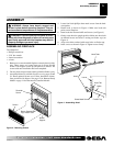
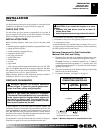
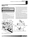
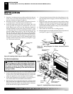
10. Attach wood base to floor with two 1
3
/4" black screws pro-
vided (see Figure 13). If the floor is concrete use anchor method
(see Attaching Wood Base to Solid Floor, page 17).
11. Install gas line. See Connecting To Gas Supply, pages 17 and 18.
12. Check for leaks. See Checking Gas Connections, page 19.
13. Place mantel around fireplace. Be careful not to damage wall
or mantel.
14. Place brass trim kit on the shoulder screws located on the side
and top of the fireplace. Firmly snap the brass trim over the
shoulder screws on fireplace (see Figure 12, page 11).
15. Adjust assembly to remove any gaps. Attach remaining two 3"
wood screws from hardware pack through openings inside of
fireplace sides into the mantel. The openings are located at top
behind the area for the brass louvers (see Figure 12, page 11).
16. Reinstall top brass louvers.
INSTALLATION
Continued
Figure 13 - Attaching Wood Base to Floor
1
3
/4" Screw
Wood Base
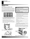
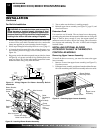
Assembling Brass Trim (Brass trim shipped with
mantel)
1. Remove packaging from three remaining pieces of brass trim.
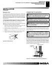
2. Locate two adjusting plates with set screws, and two shims
in the hardware packet.
3. Align shim under adjusting plate as shown in Figure 14.
4. Slide one end of adjusting plate/shim in slot on mitered edge
of top brass trim (see Figure 14).
5. Slide other end of adjusting plate/shim in slot on mitered edge
of side brass trim (see Figure 14).
6. While firmly holding edges of brass trim together, tighten both
set screws on the adjusting plate with slotted screwdriver.
7. Repeat steps 1 through 6 for other corner.
8. Set brass assembly aside for later installation.
Figure 14 - Assembling Brass Trim
Side Brass Trim
Top Brass Trim
Mitered Edge
Shim
Set
Screws
Adjusting
Plate
Slot
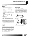
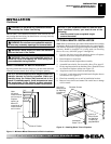
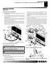
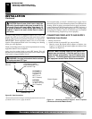
Figure 15 - Removing Upper Louver Assembly and Branch
Support
Blower Bracket
Mounting Holes
INSTALLING OPTIONAL BLOWER ACCESSORY
GA3450T IN REMOTE-READY MODELS
Removing Upper Louver Assembly and Branch
Support
To install the blower accessory, you must first remove the upper
louver assembly.
1. Lift screen off fireplace and remove log set if installed.
2. Remove 2 screws from each side of branch support and pull
branch support out (see Figure 15).
3. Remove 4 brass-plated screws from upper louver assembly
(see Figure 15). Save these screws.
4. Pull upper louver assembly straight out from the cabinet. Be care-
ful not to scratch the paint. Set louver assembly and screws aside.
5. Open lower louver door by swinging door down (see Figure 16,
page 13).
Upper Louver
Assembly
Branch Support
INSTALLATION
Optional Mantel Installation (Cont.)
Installing Blower Accessory GA3450T in Remote-Ready Models