


Special offers from our partners!

Find Replacement BBQ Parts for 20,308 Models. Repair your BBQ today.

107032-01H
For more information, visit www.desatech.com
For more information, visit www.desatech.com
20
INSTALLATION
Continued
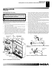
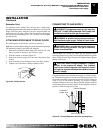
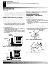
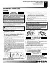
Figure 34 - Checking Gas Joints (Propane/LP Only)
Propane/LP
Supply
Tank
Equipment
Shutoff Valve
Equipment
Shutoff Valve
Gas Meter
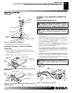
Figure 35 - Checking Gas Joints (Natural Gas Only)
INSTALLATION
Checking Gas Connections (Cont.)
Optional Wireless Hand-Held Remote Control Accessories [Remote-Ready Models Only]
3. Check all joints from gas meter to equipment shutoff valve for
natural gas or propane/LP supply to equipment shutoff valve
for propane/LP (see Figures 34 or 35). Apply noncorrosive
leak detection fluid to all joints. Bubbles forming show a leak.
4. Correct all leaks at once.
Pressure Testing Fireplace Gas Connections
1. Open equipment shutoff valve (see Figure 33, page 19).
2. Open main gas valve located on or near gas meter for natural
gas or open propane/LP supply tank valve.
3. Make sure control knob of fireplace is in the OFF position.
4. Check all joints from equipment shutoff valve to gas regulator
(Thermostat-Controlled Models), or to gas control valve (Remote-
Ready Models) (see Figures 34 or 35). Apply noncorrosive leak
detection fluid to all joints. Bubbles forming show a leak.
5. Correct all leaks at once.
6. Light fireplace (see Operating Fireplace, pages 23 through 27).
Check all other internal joints for leaks.
7. Turn off fireplace (see To Turn Off Gas to Appliance, page 24
for Thermostat-Controlled Models or page 25 for Remote-
Ready Models).
OPTIONAL WIRELESS HAND-HELD REMOTE
CONTROL ACCESSORIES
Remote-Ready Models Only
(GHRCB Series & GHRCTB Series)
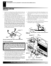
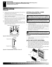
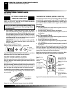
Installing Receiver
1. Remove screws.
2. Disconnect switch wires from the control valve.
3. Remove switch plate (see Figure 36). Discard switch plate
after removing. Save the screws.
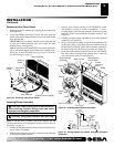
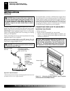
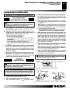
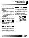
4. Locate the battery clip mounted on the back of the receiver
(see Figure 37).
5. Slide 9-volt battery (not included) through the clip.
6. Attach the terminal wires to the battery (see Figure 37).
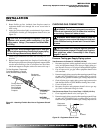
7. Connect wires as shown in Figure 38, page 21.
8. Install remote receiver unit onto fireplace base using the two
screws removed in step one (see Figure 38, page 21).
Figure 36 - Switch Plate and Wiring Harness
Figure 37 - Attaching Battery to Receiver
Battery Clip
9-Volt Battery
Receiver
Terminal
Wires
Screw
Switch Plate
Black
Wire
Red Wire
Gas Regulator or
Gas Control Valve
Gas Regulator or
Gas Control Valve