


Special offers from our partners!

Find Replacement BBQ Parts for 20,308 Models. Repair your BBQ today.
www.desatech.com
116658-01A
20
INSTALLATION
Continued
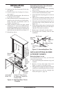
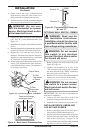
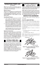
4. Gently remove the cover of the thermostat
from the base. Grasp the sides of the cover
firmly and pull to separate from the base.
5.
Feed the electrical wires through the rectangular
slots on each side of the base (see Figure 31).
WARNING: Do not con-
nect the thermostat to a power
source. Electrical shock and/or
a fire hazard will occur.
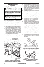
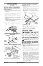
6. Connect one bare wire end to each terminal
(“W” and “R”) of the thermostat base (see
Figure 32).
7. Install the base onto the wall with the provided
screws.
8. Move the temperature adjustment back and forth
to insure the bimetal is free from restrictions.
9. Replace the cover onto the base. (Upon in-
stallation, the thermostat must be allowed to
stabilize at room temperature for a minimum
of 30 minutes for proper operation).
10. Set the temperature adjustment to the desired
setting. This thermostat has been electroni
-
cally calibrated at the factory. No adjustment
or leveling is necessary.
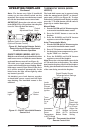
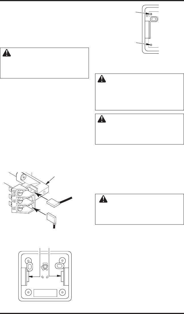
Figure 31 - Back View of Thermostat Base
Feed wires through
rectangular slots
W
R
Figure 32 - Thermostat Base Terminals
“W” and “R”
Terminal “W”
Terminal “R”
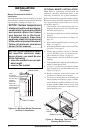
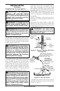
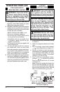
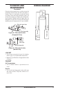
Figure 30 - Connecting Wire Terminals
To Wall
Thermostat
or Switch
To Wall
Thermostat
or Switch
Control Valve
OPTIONAL WALL SWITCH - GWMS2
WARNING: Read and fol-
low installation instructions.
Installation should be done by
a qualified installer familiar with
low-voltage wiring procedures.
WARNING: Do not connect
this switch to any electrical
source! Electrical shock and/or
fire hazard will occur.
1. Remove jumper wire from control valve (see
Figure 26, page 19).
2. Connect one terminal of 25 ft. wire to the
“TH” terminal on the control valve. Connect
the other terminal to the “THTP” terminal on
the control valve. See Figure 30.
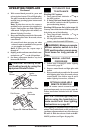
3.
Route the 25 ft. wire to a convenient location to
mount your wall switch (no outside walls).
WARNING: Do not connect
the switch to a power source.
Electrical shock and/or fire haz-
ard will occur.
IMPORTANT: The wire may be shortened but
must not be lengthened.
4. Connect one bare wire end to each of the
terminals of the provided wall switch.
5. Install the wall switch and cover in the wall.
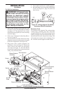
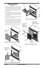
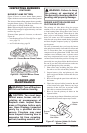
INSTALLING BRICK LINERS AND
LOG SET AND SCREEN
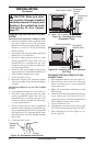
1. Remove packaging from brick liners previ-
ously removed from behind top louver.
2. Place rear brick liner against back of firebox.
The left and right brick liners will hold this
liner in place (see Figure 33, psage 21). Be
sure to hold the rear brick liner while installing
the sides so it will not fall forward.