


Special offers from our partners!

Find Replacement BBQ Parts for 20,308 Models. Repair your BBQ today.

108795-01M
For more information, visit www.desatech.com
14
INSTALLATION
Continued
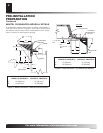
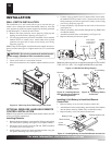
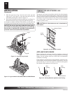
Figure 31 - Installing Logs 5 and 6
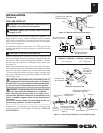
Figure 32 - Logs Installed for M42, M42P, VM42 and VM42P Models
Log 6
Log 5
Notch
Log 1
Log 2B
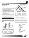
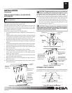
COMBUSTION AIR KIT MODEL AK4
(OPTIONAL)
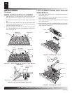
The outside air kit may be installed on the left side of the fireplace
only. The vent can be installed through any outside wall a minimum
of three feet below fireplace termination cap. The handle to operate
the damper door for the outside air inlet will be located inside the
left “screen pocket” of the firebox (see Figure 33). Pull the handle
to open or push to close.
CAUTION: Air inlet ducts are not to terminate in
attic space.
Figure 33 - Air Kit Handle Location
Air Kit
Handle
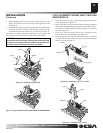
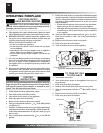
Side
Framing
Side
Framing
Caulk Here
Pack Insulation
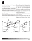
Figure 34 - Sealing Between Appliance and Framing
Screen Pocket
5. Place the upper end of log 5 into the notch on the top inner
right of log 1 (see Figure 31). Rest the lower end of log 5 on
the middle grate finger as shown in Figure 32.
6. Place log 6 into the notch on the top right of log 1 (see Figure 31).
Rest the lower end of log 6 on top of log 2B (see Figure 32).
As an option to enhance the look of the hearth, you may place the
lava rock provided around the front and sides of the burner pan.
NOTICE: Do not put lava rock inside the burner pan or
around the air mixer fitting. Placing lava rock inside the
burner pan or blocking the openings of the propane/LP
air-mixer could cause performance problems.
APPLIANCE ENCLOSURE
Before finishing the enclosure around the appliance, inspect all
joints around the outer surround. Any gaps between the nailing
flanges and the framing should be sealed with noncombustible
insulation or caulking.
If the appliance is mounted on a raised platform, it must be a con-
tinuous surface and not on blocks without a solid surface. This will
prevent the entry of cold air by means of conduction through the
total bottom of the appliance (see Figure 34).