


Special offers from our partners!

Find Replacement BBQ Parts for 20,308 Models. Repair your BBQ today.

5
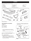
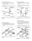
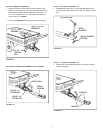
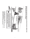
FIGURE 5
STEP 4: (S
EE FIGURE
4
)
• Assemble the hitch bracket to the front tongue using
two 3/8" x 1" hex bolts (B) and 3/8" hex nylock nuts
(L).
Tighten.
• Assemble the leg stand bracket to the front tongue
using two 5/16" x 1" hex bolts (C) and 5/16" nylock
nuts (K).
Tighten.
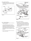
FIGURE 3
STEP 2: (S
EE FIGURE
2
)
• Assemble the latch lock subassembly to the rear
tongue using two 1/4" x 1" hex bolts (E) and 1/4"
nylock nuts (J).
Tighten.
• Assemble the plastic cap (O) to the front end of the
rear tongue.
STEP 3: (S
EE FIGURE
3
)
• Lay the rear tongue (open side facing up) onto the
Wheel Support. Assemble the axle through the wheel
support and the second hole from the end of the
tongue.
FIGURE 2
FRONT
TONGUE
(B) 3/8" x 1"
HEX BOLT
(L) 3/8" NYLOCK NUT
HITCH
BRACKET
LEG STAND
BRACKET
(C) 5/16" x 1"
HEX BOLT
(K) 5/16" NYLOCK NUT
FIGURE 4
STEP 5: (S
EE FIGURE
5
)
• Place the front tongue inside the rear tongue as
shown in fi gure 5. Fasten the tongues together using
a 3/8" x 4" hex bolt (A) and a 3/8" nylock nut (L).
Tighten,
leaving the nut just loose enough that the
tongues can pivot freely.
• Insert the 3/8" x 4" clevis pin (G) through the tongues
and secure with a 1/8" hairpin cotter (M).
LATCH LOCK
SUB-ASSEMBLY
(E) 1/4" x 1"
HEX BOLT
(J) 1/4" NYLOCK NUT
REAR
TONGUE
(O) PLASTIC CAP
WHEEL
SUPPORT
REAR
TONGUE
AXLE
FRONT
TONGUE
(L) 3/8"
NYLOCK NUT
(A) 3/8" x 4"
HEX BOLT
(G) 3/8" x 4"
CLEVIS PIN
(M) 1/8" HAIRPIN
COTTER