


Special offers from our partners!

Find Replacement BBQ Parts for 20,308 Models. Repair your BBQ today.
Buy Weber Grill Parts. It couldn't be easier. Find your Weber parts here.
i) To reinstall the burners, reverse steps c) through g).
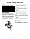
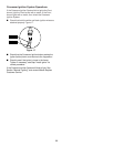
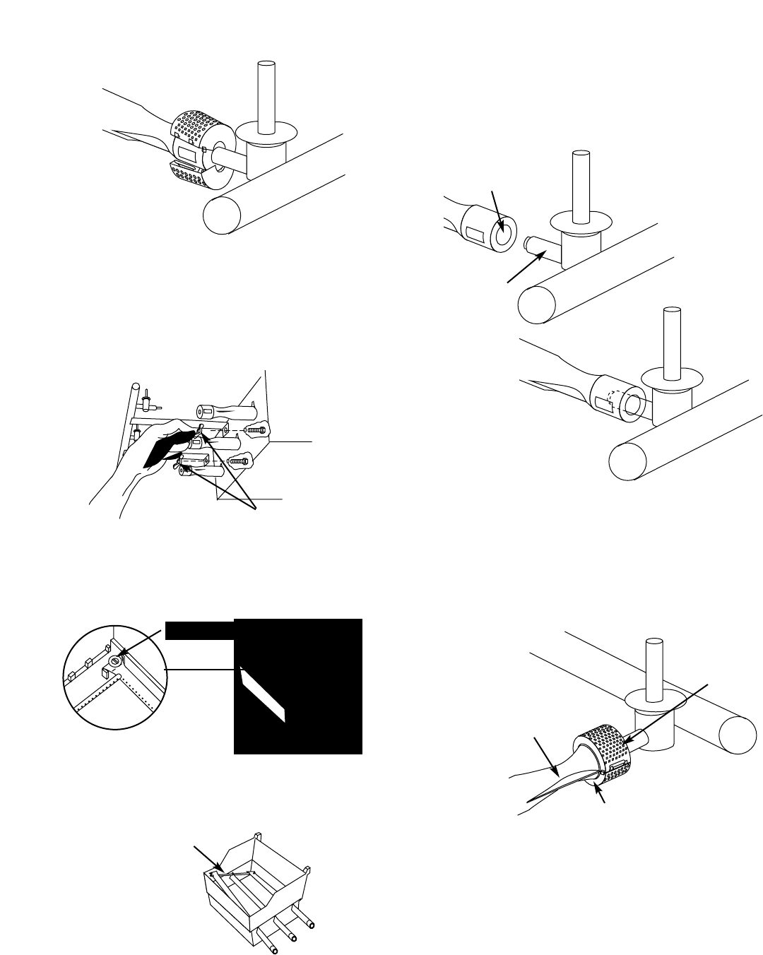
ƽCAUTION: The burner openings must be positioned
properly over the valve orifices. Figure 15 (a).
Check proper assembly before fastening manifold in place.
Figure 15 (b).
34
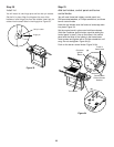
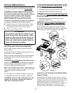
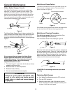
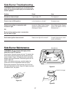
e) Disconnect gas supply line and side burner.
f) Remove the manifold bracket and unscrew the two
wing nuts that hold the manifold to the cooking box.
Pull the manifold and valve assembly out of the
burners and carefully set it down. Figure 12.
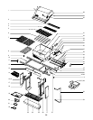
View from behind
cooking box
Wing nuts
Figure 12
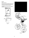
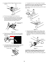
Guide screw
Crossover tube
Figure 14
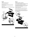
Venturi fin
Figure 16
Figure 15
(a)
(b)
Check fit
around valve
Burner
opening
Valve
orifice
Check fit around burner
Figure 11
d) Unlatch the Spider Stopper Guards and remove.
Figure 11.
h) Lift and twist the burner assembly slightly, to separate
the crossover tube from the burners. Figure 14.
Remove the burners from the cooking box.
g) Slide the burner assembly out from under the guide
screw and washer in the corners of the cooking box.
Figure 13.
j) Reinstall the Spider Stopper Guards. Slightly rotate
the Spider Stopper Guards so that the seams are in
line with the Venturi fins. There should be no gaps in
the seams or in the fit around the burners and valves.
Figure 16.
ƽCAUTION: If the Spider Stopper Guards do not fit
tightly, contact Weber-Stephen Customer Service.
k) Reconnect gas supply line. See “Check for gas leaks”.
Figure 13